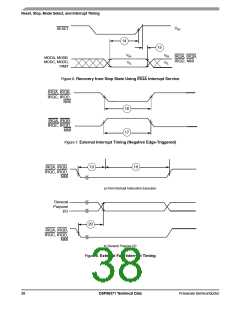
External Clock Operation
10
External Clock Operation
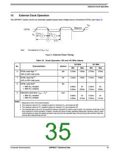
The DSP56371 system clock is an externally supplied square wave voltage source connected to EXTAL (see Figure 4).
.
V
IH
Midpoint
EXTAL
ETH
ETL
V
IL
6
7
8
ETC
Note:
The midpoint is 0.5 (VIH + VIL).
Figure 4. External Clock Timing
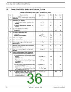
Table 18. Clock Operation 150 and 181 MHz Values
150 MHz
181 MHz
No.
Characteristics
Symbol
Min
Max
Min
Max
6
EXTAL input high 1,2
Eth
3.33ns
100ns
2.75ns
100ns
(40% to 60% duty cycle)
7
8
EXTAL input low1,2
Etl
3.33ns
100ns
2.75ns
100ns
(40% to 60% duty cycle)
EXTAL cycle time2
Etc
• With PLL disabled
• With PLL enabled
6.66ns
6.66ns
inf
5.52ns
5.52ns
inf
200ns
200ns
3
9
Instruction cycle time= ICYC = TC
Icyc
• With PLL disabled
• With PLL enabled
6.66ns
6.66ns
inf
5.52ns
5.52ns
inf
13.0ns
13.0ns
Notes:
1. Measured at 50% of the input transition
2. The maximum value for PLL enabled is given for minimum VCO and maximum MF.
3. The maximum value for PLL enabled is given for minimum VCO and maximum DF.
4. The indicated duty cycle is for the specified maximum frequency for which a part is rated. The minimum clock high or low
time required for correct operation, however, remains the same at lower operating frequencies; therefore, when a lower
clock frequency is used, the signal symmetry may vary from the specified duty cycle as long as the minimum high time
and low time requirements are met.
Freescale Semiconductor
DSP56371 Technical Data
35

 FREESCALE [ Freescale ]