Freescale Semiconductor, Inc.
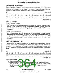
8.4.2 Interrupt Register (IR)
The IR contains the priority level for the timer interrupt request and the 8-bit vector number
of the interrupt. The register can be read or written to at any time while in supervisor mode
and while the timer module is enabled (i.e., the STP bit in the MCR is cleared).
IR
$604, $644
15
14
0
13
0
12
0
11
0
10
9
8
7
6
5
4
3
2
1
0
0
IL2
IL1
IL0
IVR7
IVR6
IVR5
IVR4
IVR3
IVR2
IVR1
IVR0
RESET:
0
0
0
0
0
0
0
0
0
0
0
0
1
1
1
1
Supervisor Only
Bits 15–11—Reserved
IL2–IL0—Interrupt Level Bits
Each module that can generate interrupts has an interrupt level field. The priority level
encoded in these bits is sent to the CPU32 on the appropriate IRQ≈ signal. The CPU32
uses this value to determine servicing priority. See Section 5 CPU32 for more
information.
IV7–IV0—Interrupt Vector Bits
Each module that can generate interrupts has an interrupt vector (IV) field. This 8-bit
number indicates the offset from the base of the vector table where the address of the
exception handler for the specified interrupt is located. The IV field is reset to $0F,
which indicates an uninitialized interrupt condition. See Section 5 CPU32 for more
information.
8.4.3 Control Register (CR)
The CR controls the operation of the timer. The register can always be read or written
when the timer module is enabled (i.e., the STP bit in the MCR is cleared). Changing the
contents of the CR should only be attempted when the timer is disabled (the SWR bit in
the CR is cleared). Changing the CR while the timer is running may produce unpredictable
results.
CR
15
$606, $646
14
13
12
11
10
9
8
7
6
5
4
3
2
1
0
SWR
IE2
IE1
IE0
TGE
PCLK
CPE
CLK
POT2
POT1
POT0 MODE2 MODE1 MODE0
OC1
OC0
RESET:
0
0
0
0
0
0
0
0
0
0
0
0
0
0
0
0
Supervisor/User
SWR—Software Reset
1 = Removes the software reset.
0 = A software reset is performed by first clearing this bit and then clearing the TO,
TG, and TC bits in the SR. The prescaler is loaded with $FF, the counter is set to
$0000, and the SR COM bit is cleared. When this bit is zero, the timer is
disabled.
8- 20
MC68340 USER’S MANUAL
MOTOROLA
For More Information On This Product,
Go to: www.freescale.com

 FREESCALE [ Freescale ]