Freescale Semiconductor, Inc.
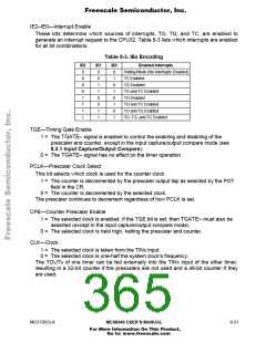
IE2–IE0—Interrupt Enable
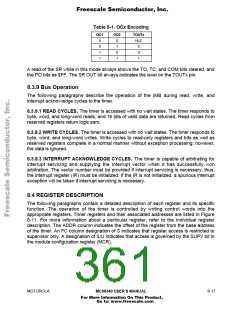
These bits determine which sources of interrupts, TO, TG, and TC, are enabled to
generate an interrupt request to the CPU32. Table 8-3 lists which interrupts are enabled
for all bit combinations.
Table 8-3. IEx Encoding
IE2
0
IE1
0
IE0
0
Enabled Interrupts
Polling Mode (No Interrupts Enabled)
TC Enabled
0
0
1
0
1
0
TG Enabled
0
1
1
TG and TC Enabled
TO Enabled
1
0
0
1
0
1
TO and TC Enabled
TO and TG Enabled
TO, TG, and TC Enabled
1
1
0
1
1
1
TGE—Timing Gate Enable
1 = The TGATE≈ signal is enabled to control the enabling and disabling of the
prescaler and counter, except in the input capture/output compare mode (see
8.3.1 Input Capture/Output Compare).
0 = The TGATE≈ signal has no effect on the timer operation.
PCLK—Prescaler Clock Select
This bit selects which clock is used for the counter clock.
1 = The counter is decremented by the prescaler output tap as selected by the POT
field in the CR.
0 = The counter is decremented by the selected clock.
The prescaler continues to decrement regardless of how PCLK is set.
CPE—Counter Prescaler Enable
1 = The selected clock is enabled. If the TGE bit is set, then TGATE≈ must also be
asserted (except in the input capture/output compare mode).
0 = The selected clock is held high, halting the prescaler and counter.
CLK—Clock
1 = The selected clock is taken from the TINx input.
0 = The selected clock is one-half the system clock's frequency.
The TOUTx of one timer can be fed externally into the TINx input of the other timer,
resulting in a 32-bit counter if the prescalers are not used and a 48-bit counter if they
are used.
MOTOROLA
MC68340 USER’S MANUAL
8- 21
For More Information On This Product,
Go to: www.freescale.com

 FREESCALE [ Freescale ]