Freescale Semiconductor, Inc.
STP—Stop bit
1 = Setting the STP bit stops all clocks within the timer module except for the clock
from the IMB. The clock from the IMB remains active to allow the CPU32 access
to the MCR. The clock stops on the low phase of the clock and remains stopped
until the STP bit is cleared by the CPU32 or a hardware reset. Accesses to timer
module registers while in stop mode produce a bus error. The timer module
should be disabled in a known state prior to setting the STP bit; otherwise,
unpredictable results may occur. The STP bit should be set prior to executing the
LPSTOP instruction to reduce overall power consumption.
0 = The timer operates in normal mode.
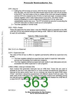
FRZ1, FRZ0—Freeze
These bits determine the action taken when the FREEZE signal is asserted on the IMB,
when the CPU32 has entered background debug mode. Table 8-2 lists the action taken
for each bit combination.
Table 8-2. FRZx Control Bits
FRZ1
FRZ0
ACTION
Ignore FREEZE
0
0
1
1
0
1
0
1
Reserved (FREEZE ignored)
Execution Freeze
Execution Freeze
Bits 12–8, 6–4—Reserved
SUPV—Supervisor/User
The value of this bit has no effect on registers permanently defined as supervisor-only
access.
1 = The timer registers defined as supervisor/user reside in supervisor data space
and are only accessible from supervisor programs.
0 = The timer registers defined as supervisor/user reside in user data space and are
accessible from either supervisor or user programs.
IARB3–IARB0—Interrupt Arbitration Bits
Each module that generates interrupts has an IARB field. These bits are used to
arbitrate for the bus in the case that two or more modules simultaneously generate an
interrupt at the same priority level. No two modules can share the same IARB value.
(Timer 1 and timer 2 should be programmed with different values if both are used.) The
reset value of the IARB field is $0, which prevents this module from arbitrating during
the interrupt acknowledge cycle. The system software should initialize the IARB field to
a value from $F (highest priority) to $1 (lowest priority).
MOTOROLA
MC68340 USER’S MANUAL
8- 19
For More Information On This Product,
Go to: www.freescale.com

 FREESCALE [ Freescale ]