Freescale Semiconductor, Inc.
Periodic interrupt generation can be accomplished by enabling the TO, TG, and/or TC bits
in the SR to generate interrupts by programming the IE bits of the CR. When enabled, the
programmed IRQ≈ signal is asserted whenever the specified bits are set.
TOUTx signal transitions can be controlled by writing new values into the COM. Caution
must be exercised when accessing the COM. If it were to be accessed simultaneously by
the compare logic and by a write, the old compare value may actually get compared to the
counter value.
8.3.2 Square-Wave Generator
This mode can be used for generating both square-wave output and periodic interrupts.
The square wave is generated by counting down from the value in the PREL1 to timeout
(counter value of $0000). TOUTx changes state on each timeout as programmed. This
mode can be selected by programming the CR MODEx bits to 001.
The timer is enabled by setting the SWR and CPE bits in the CR and, if TGATE≈ is
programmed to control the enabling and disabling of the counter (TGE bit set in the CR),
then asserting TGATE≈. When the timer is enabled, the ON bit in the SR is set. On the
next falling edge of the counter clock, the counter is loaded with the value stored in the
PREL1 (N). With each successive falling edge of the counter clock, the counter
decrements. The time between enabling the timer and the first timeout can range from N
to N + 1 periods. When TGATE≈ is used to enable the timer, the enabling of the timer is
asynchronous; however, if timing is carefully considered, the time to the first timeout can
be known. For additional details on timing, see Section 11 Electrical Characteristics.
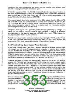
TOUTx behaves as a square wave when the OCx bits of the CR are programmed for
toggle mode. A timeout occurs every N + 1 periods (allowing for the zero cycle), resulting
in a change of state on TOUTx (see Figure 8-5). The SR OUT bit reflects the level of
TOUTx. If this mode is used to generate periodic interrupts, TOUTx may be enabled if a
square wave is also desired.
COUNTER
CLOCK
COUNTER
TOUT
3
0
0
3
2
1
0
3
2
1
0
3
2
1
0
N + 1
N + 1
N: N + 1
ENABLE
TIMEOUT
TIMEOUT
TIMEOUT
MODEx Bits in Control Register = 001
Preload 1 Register = N = 3
OCx Bits in Control Register = 01
Figure 8-5. Square-Wave Generator Mode
If TGATE≈ is negated when it is enabled to control the timer (TGE = 1), the prescaler and
counter are disabled. Additionally, the SR TG bit is set, indicating that TGATE≈ was
negated. The SR ON bit is cleared, indicating that the timer is disabled. If TGATE≈ is
8- 8
MC68340 USER’S MANUAL
MOTOROLA
For More Information On This Product,
Go to: www.freescale.com

 FREESCALE [ Freescale ]