Freescale Semiconductor, Inc.
immediately after the SWR and CPE bits in the CR are set. The SR TG bit cannot be set.
At all times, the TGL bit in the SR reflects the level of TGATE≈.
The width of the pulse generated on TOUTx (the value in PREL2) can be changed while
the counter is counting down from the value in PREL1. Caution must be used because, if
PREL2 is accessed simultaneously by the counting logic and a CPU32 write, the old
PREL2 value may actually get loaded into the counter at timeout.
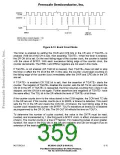
8.3.5 Pulse-Width Measurement
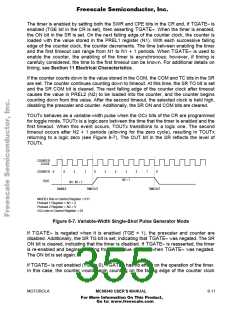
This mode is used to count the clock cycles during a particular event (see Figure 8-8). The
event is defined by the assertion and negation of TGATE≈. When TGATE≈ is asserted,
the counter begins counting down from $FFFF. When TGATE≈ is negated, the counter
stops counting and holds the value at which it stopped. Further assertions and negations
of TGATE≈ have no effect on the counter. This mode can be selected by programming
the CR MODEx bits to 100.
The timer is enabled by setting the SWR, CPE, and TGE bits in the CR. Asserting
TGATE≈ starts the counter. When the timer is enabled, the SR ON bit is set. On the next
falling edge of the counter clock, the counter is loaded with the value $FFFF. With each
successive falling edge of the counter clock, the counter decrements. The PREL1 and
PREL2 registers are not used in this mode.
When TGATE≈ is negated, the SR TG bit is set, the ON bit is negated, and the prescaler
and counter are disabled. Subsequent transitions on TGATE≈ do not re-enable the
counter. The TGL bit in the SR reflects the level of TGATE≈ at all times.
COUNTER
CLOCK
COUNTER
0
f
f
f
f
f
f
f
e
f
f
f
f
f
f
f
f
f
f
f
f
d
c
b
b
TGATE
MEASURED PULSE
ENABLE
START
COUNTING
STOP
COUNTING
NO EFFECT
MODEx Bits in Control Register = 100
TGE Bit of Control Register = 1
Figure 8-8. Pulse-Width Measurement Mode
If the counter counts down to the value stored in the COM register, the COM and TC bits
in the SR are set. If the counter counts down to $0000, a timeout is detected. This sets the
SR TO, and the clears the COM bit. At timeout, the next falling edge of the counter clock
8- 12
MC68340 USER’S MANUAL
MOTOROLA
For More Information On This Product,
Go to: www.freescale.com

 FREESCALE [ Freescale ]