Freescale Semiconductor, Inc.
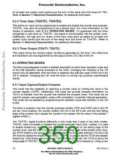
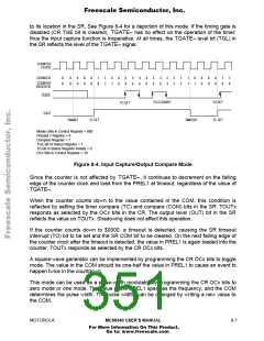
to its location in the SR. See Figure 8-4 for a depiction of this mode. If the timing gate is
disabled (CR TGE bit is cleared), TGATE≈ has no effect on the operation of the timer;
thus the input capture function is inoperative. At all times, the TGATE≈ level bit (TGL) in
the SR reflects the level of the TGATE≈ signal.
COUNTER
CLOCK
COUNTER
0
0
0
0
0
8
0
8
8
7
8
7
7
6
7
6
6
5
6
5
6
4
6
4
6
3
6
3
6
2
3
2
2
1
2
1
1
0
1
0
0
8
0
8
8
7
8
7
8
COUNTER
REGISTER
0
TGATE
TOUT
TG CLEARED
TG SET
TC SET
TG SET
ENABLE
TC SET
TIMEOUT
Modex Bits in Control Register = 000
Preload 1 Register = 8
Compare Register = 7
TGE Bit of Status Register = 1
TG Bit in Status Register Initially = 0
OCx Bits in Control Register = 10
Figure 8-4. Input Capture/Output Compare Mode
Since the counter is not affected by TGATE≈, it continues to decrement on the falling
edge of the counter clock and load from the PREL1 at timeout, regardless of the value of
TGATE≈.
When the counter counts down to the value contained in the COM, this condition is
reflected by setting the timer compare (TC) and compare (COM) bits in the SR. TOUTx
responds as selected by the OCx bits in the CR. The output level (OUT) bit in the SR
reflects the value on TOUTx. Shadowing does not affect this operation.
If the counter counts down to $0000, a timeout is detected, causing the SR timeout
interrupt (TO) bit to be set and the SR COM bit to be cleared. On the next falling edge of
the counter clock after the timeout is detected, the value in PREL1 is again loaded into the
counter. TOUTx responds as selected by the CR OCx bits.
A square-wave generator can be implemented by programming the CR OCx bits to toggle
mode. The value in the COM should be one-half the value in PREL1 to cause an event to
happen twice in the countdown.
This mode can be used as a pulse-width modulator by programming the CR OCx bits to
zero mode or one mode. The value in the PREL1 specifies the frequency, and the COM
determines the pulse width. The pulse widths can be changed by writing a new value to
the COM.
MOTOROLA
MC68340 USER’S MANUAL
8- 7
For More Information On This Product,
Go to: www.freescale.com

 FREESCALE [ Freescale ]