Freescale Semiconductor, Inc.
The timer is enabled by setting both the SWR and CPE bits in the CR and, if TGATE≈ is
enabled (TGE bit in the CR is set), then asserting TGATE≈. When the timer is enabled,
the ON bit in the SR is set. On the next falling edge of the counter clock, the counter is
loaded with the value stored in the PREL1 register (N1). With each successive falling
edge of the counter clock, the counter decrements. The time between enabling the timer
and the first timeout can range from N1 to N1 + 1 periods. When TGATE≈ is used to
enable the counter, the enabling of the timer is asynchronous; however, if timing is
carefully considered, the time to the first timeout can be known. For additional details on
timing, see Section 11 Electrical Characteristics.
If the counter counts down to the value stored in the COM, the COM and TC bits in the SR
are set. The counter continues counting down to timeout. At this time, the SR TO bit is set
and the SR COM bit is cleared. The next falling edge of the counter clock after timeout
causes the value in PREL2 (N2) to be loaded into the counter, and the counter begins
counting down from this value. After the second timeout, the selected clock is held high,
disabling the prescaler and counter. Additionally, the SR ON and COM bits are cleared.
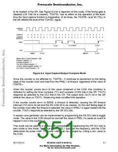
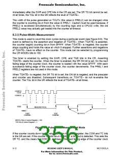
TOUTx behaves as a variable-width pulse when the OCx bits of the CR are programmed
for toggle mode. TOUTx is a logic zero between the time that the timer is enabled and the
first timeout. When this event occurs, TOUTx transitions to a logic one. The second
timeout occurs after N2 + 1 periods (allowing for the zero cycle), resulting in TOUTx
returning to a logic zero (see Figure 8-7). The OUT bit in the SR reflects the level of
TOUTx.
COUNTER
CLOCK
COUNTER
TOUT
0
0
2
1
0
5
4
3
2
1
0
N2 + 1
N1: N1 + 1
ENABLE
TIMEOUT
TIMEOUT
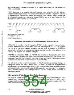
MODEx Bits in Control Register = 011
Preload 1 Register = N1 = 2
Preload 2 Register = N2 = 5
OCx bits in Control Register = 01
Figure 8-7. Variable-Width Single-Shot Pulse Generator Mode
If TGATE≈ is negated when it is enabled (TGE = 1), the prescaler and counter are
disabled. Additionally, the SR TG bit is set, indicating that TGATE≈ was negated. The SR
ON bit is cleared, indicating that the timer is disabled. If TGATE≈ is reasserted, the timer
is re-enabled and begins counting from the value attained when TGATE≈ was negated.
The ON bit is set again.
If TGATE≈ is not enabled (TGE = 0), TGATE≈ has no effect on the operation of the timer.
In this case, the counter would begin counting on the falling edge of the counter clock
MOTOROLA
MC68340 USER’S MANUAL
8- 11
For More Information On This Product,
Go to: www.freescale.com

 FREESCALE [ Freescale ]