Freescale Semiconductor, Inc.
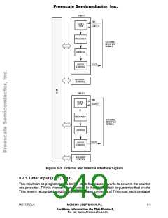
for at least one system clock period plus the sum of the setup and hold times for TINx.
Refer to Section 11 Electrical Characteristics, for additional information.
8.2.2 Timer Gate (TGATE1, TGATE2)
This active-low input can be programmed to enable and disable the counter and prescaler.
TGATE≈ may also be programmed to be a simple input. For more information on the
modes of operation, refer to 8.3 OPERATING MODES. To guarantee that the timer
recognizes a valid level on TGATE≈, the signal is synchronized with the system clock.
Additionally, the high and low levels of this input must each be stable for at least one
system clock period plus the sum of the setup and hold times for TGATE≈. Refer to
Section 11 Electrical Characteristics, for additional information.
8.2.3 Timer Output (TOUT1, TOUT2)
This output drives the various output waveforms generated by the timer. The initial level
and transitions can be programmed by the output control (OC) bits in the CR.
8.3 OPERATING MODES
The following paragraphs contain a detailed description of each timer operation mode and
of the IMB operation during accesses to the timer. Changing the contents of the CR
should only be attempted when the timer is disabled (the software reset (SWR) bit in the
CR is cleared). Changing the CR while the timer is running may produce unpredictable
results.
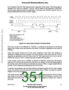
8.3.1 Input Capture/Output Compare
This mode has the capability of capturing a counter value by holding the value in the
counter register (CNTR). Additionally, this mode can provide compare information via
TOUTx to indicate when the counter has reached the compare value. This mode can be
used for square-wave generation, pulse-width modulation, or periodic interrupt generation.
This mode can be selected by programming the operation mode bits (MODEx) in the CR
to 000.
The timer is enabled when the counter prescaler enable (CPE) and SWRx bits in the CR
are set. Once enabled, the counter enable (ON) bit in the SR is set, and the next falling
edge of the counter clock causes the counter to be loaded with the value in the preload 1
register (PREL1).
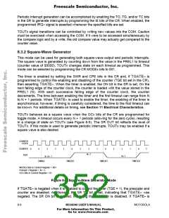
The TGATE≈ signal functions differently in this mode than it does in the other modes.
TGATE≈ does not enable or disable the counter/prescaler input clock; instead, it is used
to disable shadowing. Normally, the counter is decremented on the falling edge of the
counter clock, and the CNTR is updated on the next rising edge of the system clock; thus,
the CNTR shadows the actual value of the counter. The timer gate interrupt (TG) bit in the
SR must be cleared for shadowing to occur. TGATE≈ is used to set the TG bit and disable
shadowing. If the timing gate is enabled (TGE bit of the CR is set), the TG bit is set by the
rising edge of TGATE≈. Shadowing is disabled until the TG bit is cleared by writing a one
8- 6
MC68340 USER’S MANUAL
MOTOROLA
For More Information On This Product,
Go to: www.freescale.com

 FREESCALE [ Freescale ]