Freescale Semiconductor, Inc.
— Pulse-Width Measurement
— Period Measurement
— Event Counting
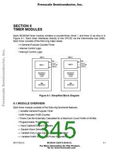
• Seven Maskable Interrupt Conditions Based on Programmable Events
8.1.1 Timer and Counter Functions
The term 'timer' is used to reference either timer 1 or timer 2, since the two are functionally
equivalent.
The timer can perform virtually any application traditionally assigned to timers and
counters. The timer can be used to generate timed events that are independent of the
timing errors to which real-time programmed microprocessors are susceptible—for
example, those of dynamic memory refreshing, DMA cycle steals, and interrupt servicing.
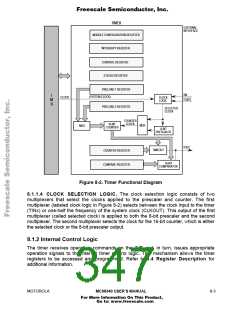
The timer has several functional areas: an 8-bit countdown prescaler, a 16-bit
downcounter, timeout logic, compare logic, and clock selection logic. Figure 8-2 shows a
functional diagram of the timer module.
8.1.1.1 PRESCALER AND COUNTER. The counter can be driven directly by the selected
clock or the prescaler output. Both the counter and prescaler are updated on the falling
edge of the clock. During reset, the prescaler is set to $FF, and the counter is set to
$0000. The counter is loaded with a programmed value on the first falling edge of the
counter clock after the timer is enabled and again when a timeout occurs (counter reaches
$0000). The prescaler and counter can be used as one 24-bit counter by enabling the
prescaler and selecting the divide-by-256 prescaler output. Refer to 8.4 Register
Description for additional information on how to program the timer.
8.1.1.2 TIMEOUT DETECTION. Timeout is achieved when all 16 stages of the counter
transition to zero, a counter value of $0000. Timeout is a defined counter event which
triggers specific actions depending upon the programmed mode of operation. Refer to 8.3
Operating Modes for descriptions of the individual modes.
8.1.1.3 COMPARATOR. The comparator block compares the value in the 16-bit compare
register (COM) with the output of the 16-bit counter. When an exact match is detected,
bits in the status register (SR) are set to indicate this condition. When in the input
capture/output compare mode, a match is a defined counter event that can affect the
output of the timer (TOUTx). Refer to 8.3.1 Input Capture/Output Compare for additional
information on this mode.
8- 2
MC68340 USER’S MANUAL
MOTOROLA
For More Information On This Product,
Go to: www.freescale.com

 FREESCALE [ Freescale ]