Freescale Semiconductor, Inc.
C2
C5
C6
C6, C7, C8 ARE LOST
C8
RxD
C1
C3
C4
C7
RECEIVER
ENABLED
RxRDY
(SR0)
FFULL
(SR1)
RxRDYA
CS
R
R
R
R
R R R
R
STATUS DATA
C2
STATUS DATA
C3
STATUS DATA
C1
STATUS DATA
C4
C5
LOST
OVERRUN
(SR4)
1
RTS
RESET BY COMMAND
OPR(0) = 1
NOTES:
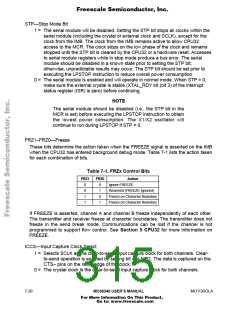
1. Timing shown for MR1(7) = 1
2. Timing shown for OPCR(4) = 1 and MR1(6) = 0
3. R = Read
4. C = Received Character
N
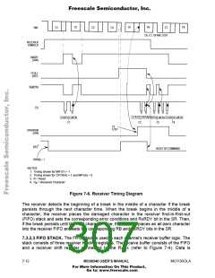
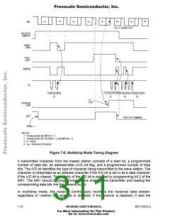
Figure 7-8. Multidrop Mode Timing Diagram
A transmitted character from the master station consists of a start bit, a programmed
number of data bits, an address/data (A/D) bit flag, and a programmed number of stop
bits. The A/D bit identifies the type of character being transmitted to the slave station. The
character is interpreted as an address character if the A/D bit is set or as a data character
if the A/D bit is cleared. The polarity of the A/D bit is selected by programming bit 2 of the
MR1. The MR1 should be programmed before enabling the transmitter and loading the
corresponding data bits into the transmit buffer.
In multidrop mode, the receiver continuously monitors the received data stream,
regardless of whether it is enabled or disabled. If the receiver is disabled, it sets the
7- 16
MC68340 USER’S MANUAL
MOTOROLA
For More Information On This Product,
Go to: www.freescale.com

 FREESCALE [ Freescale ]