Freescale Semiconductor, Inc.
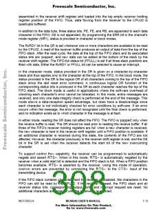
RxDx
Rx
Tx
INPUT
CPU
DISABLED
DISABLED
TxDx
OUTPUT
(a) Automatic Echo
DISABLED
DISABLED
RxDx
Rx
Tx
INPUT
CPU
TxDx
OUTPUT
(b) Local Loopback
DISABLED
DISABLED
DISABLED
DISABLED
RxDx
Rx
Tx
INPUT
CPU
TxDx
OUTPUT
(c) Remote Loopback
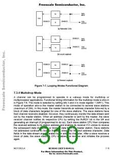
Figure 7-7. Looping Modes Functional Diagram
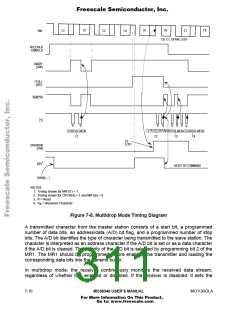
7.3.4 Multidrop Mode
A channel can be programmed to operate in a wakeup mode for multidrop or
multiprocessor applications. Functional timing information for the multidrop mode is shown
in Figure 7-8. The mode is selected by setting bits 3 and 4 in mode register 1 (MR1). This
mode of operation allows the master station to be connected to several slave stations
(maximum of 256). In this mode, the master transmits an address character followed by a
block of data characters targeted for one of the slave stations. The slave stations have
their channel receivers disabled. However, they continuously monitor the data stream sent
out by the master station. When an address character is sent by the master, the slave
receiver channel notifies its respective CPU by setting the RxRDY bit in the SR and
generating an interrupt (if programmed to do so). Each slave station CPU then compares
the received address to its station address and enables its receiver if it wishes to receive
the subsequent data characters or block of data from the master station. Slave stations
not addressed continue to monitor the data stream for the next address character. Data
fields in the data stream are separated by an address character. After a slave receives a
block of data, the slave station's CPU disables the receiver and initiates the process
again.
MOTOROLA
MC68340 USER’S MANUAL
7- 15
For More Information On This Product,
Go to: www.freescale.com

 FREESCALE [ Freescale ]