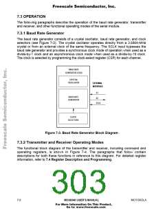
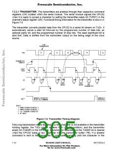
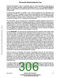
Freescale Semiconductor, Inc.
C2
C5
C6
C6, C7, C8 ARE LOST
C8
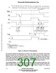
RxD
C1
C3
C4
C7
RECEIVER
ENABLED
RxRDY
(SR0)
FFULL
(SR1)
RxRDYA
CS
R
R
R
R
R R R
R
STATUS DATA
C2
STATUS DATA
C3
STATUS DATA
C1
STATUS DATA
C4
C5
LOST
OVERRUN
(SR4)
1
RTS
RESET BY COMMAND
OPR(0) = 1
NOTES:
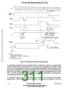
1. Timing shown for MR1(7) = 1
2. Timing shown for OPCR(4) = 1 and MR1(6) = 0
3. R = Read
4. C = Received Character
N
Figure 7-6. Receiver Timing Diagram
The receiver detects the beginning of a break in the middle of a character if the break
persists through the next character time. When the break begins in the middle of a
character, the receiver places the damaged character in the receiver first-in-first-out
(FIFO) stack and sets the corresponding error conditions and RxRDY bit in the SR. Then,
if the break persists until the next character time, the receiver places an all-zero character
into the receiver FIFO and sets the corresponding RB and RxRDY bits in the SR.
7.3.2.3 FIFO STACK. The FIFO stack is used in each channel's receiver buffer logic. The
stack consists of three receiver holding registers. The receive buffer consists of the FIFO
and a receiver shift register connected to the RxDx (refer to Figure 7-4). Data is
7- 12
MC68340 USER’S MANUAL
MOTOROLA
For More Information On This Product,
Go to: www.freescale.com

 FREESCALE [ Freescale ]