Freescale Semiconductor, Inc.
STP—Stop Mode Bit
1 = The serial module will be disabled. Setting the STP bit stops all clocks within the
serial module (including the crystal or external clock and SCLK), except for the
clock from the IMB. The clock from the IMB remains active to allow CPU32
access to the MCR. The clock stops on the low phase of the clock and remains
stopped until the STP bit is cleared by the CPU32 or a hardware reset. Accesses
to serial module registers while in stop mode produce a bus error. The serial
module should be disabled in a known state prior to setting the STP bit;
otherwise, unpredictable results may occur. The STP bit should be set prior to
executing the LPSTOP instruction to reduce overall power consumption.
0 = The serial module is enabled and will operate in normal mode. When STP = 0,
make sure the external crystal is stable (XTAL_RDY bit (bit 3) of the interrupt
status register (ISR) is zero) before continuing.
NOTE
The serial module should be disabled (i.e., the STP bit in the
MCR is set) before executing the LPSTOP instruction to obtain
the lowest power consumption. The X1/X2 oscillator will
continue to run during LPSTOP if STP = 0.
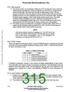
FRZ1–FRZ0—Freeze
These bits determine the action taken when the FREEZE signal is asserted on the IMB
when the CPU32 has entered background debug mode. Table 7-1 lists the action taken
for each combination of bits.
Table 7-1. FRZx Control Bits
FRZ1
FRZ0
Action
Ignore FREEZE
0
0
1
1
0
1
0
1
Reserved (FREEZE Ignored)
Freeze on Character Boundary
Freeze on Character Boundary
If FREEZE is asserted, channel A and channel B freeze independently of each other.
The transmitter and receiver freeze at character boundaries. The transmitter does not
freeze in the send break mode. Communications can be lost if the channel is not
programmed to support flow control. See Section 5 CPU32 for more information on
FREEZE.
ICCS—Input Capture Clock Select
1 = Selects SCLK as the clear-to-send input capture clock for both channels. Clear-
to-send operation is enabled by setting bit 4 in MR2. The data is captured on the
CTS≈ pins on the rising edge of the clock.
0 = The crystal clock is the clear-to-send input capture clock for both channels.
7- 20
MC68340 USER’S MANUAL
MOTOROLA
For More Information On This Product,
Go to: www.freescale.com

 FREESCALE [ Freescale ]