Freescale Semiconductor, Inc.
The reset value of the IARB field is $0, which prevents the DMA module from arbitrating
during the interrupt acknowledge cycle. The system software should initialize the IARB
field to a value from $F (highest priority) to $1 (lowest priority).
NOTE
The DMA module uses only one set of IARB bits for both
channels. A read or write to either MCR accesses the same
IARB control bits.
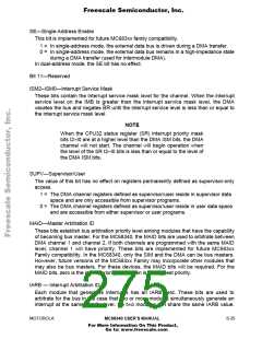
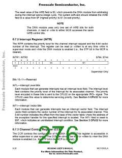
6.7.2 Interrupt Register (INTR)
The INTR contains the priority level for the channel interrupt request and the 8-bit vector
number of the interrupt. The register can be read or written to at any time while in
supervisor mode and while the DMA module is enabled (i.e., the STP bit in the MCR is
cleared).
INTR1, INTR2
$784, $7A4
15
14
13
12
0
11
0
10
0
9
8
0
7
0
6
0
5
0
4
0
3
1
2
1
0
0
0
0
INTL
INTV
RESET:
0
0
0
0
0
0
1
1
1
Supervisor Only
Bits 15–11—Reserved
INTL—Interrupt Level Bits
Each module that can generate interrupts has an interrupt level field. The interrupt level
field contains the priority level of the interrupt for its associated channel. The priority
level encoded in these bits is sent to the CPU32 on the appropriate IRQ≈ signal. The
CPU32 uses this value to determine servicing priority. See Section 5 CPU32 for more
information.
INTV—Interrupt Vector Bits
Each module that can generate interrupts has an interrupt vector field. The interrupt
vector field contains the vector number of the interrupt for its associated channel. This
8-bit number indicates the offset from the base of the vector table where the address of
the exception handler for the specified interrupt is located. The INTV field is reset to
$0F, which indicates an uninitialized interrupt condition. See Section 5 CPU32 for more
information.
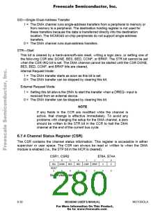
6.7.3 Channel Control Register (CCR)
The CCR controls the configuration of the DMA channel. This register is accessible in
either supervisor or user space. The CCR can always be read or written to when the DMA
module is enabled (i.e., the STP bit in the MCR is cleared).
6- 26
MC68340 USER’S MANUAL
MOTOROLA
For More Information On This Product,
Go to: www.freescale.com

 FREESCALE [ Freescale ]