Freescale Semiconductor, Inc.
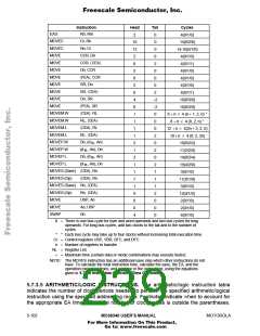
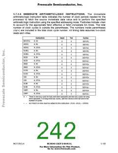
5.7.3.6 IMMEDIATE ARITHMETIC/LOGIC INSTRUCTIONS. The immediate
arithmetic/logic instruction table indicates the number of clock periods needed for the
processor to fetch the source immediate data value and to perform the specified
arithmetic/logic instruction using the specified addressing mode. Footnotes indicate when
to account for the appropriate fetch effective or fetch immediate EA times. The total
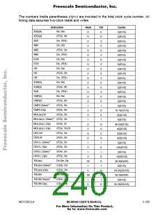
number of clock cycles is outside the parentheses. The numbers inside parentheses
(r/p/w) are included in the total clock cycle number. All timing data assumes two-clock
reads and writes.
Instruction
#, Dn
Head
Tail
0
Cycles
2(0/1/0)
2(0/1/0)
5(0/1/x)
2(0/1/0)
5(0/1/x)
2(0/1/0)
5(0/1/x)
2(0/1/0)
5(0/1/x)
2(0/1/0)
5(0/1/x)
2(0/1/0)
5(0/1/x)
2(0/1/0)
5(0/1/x)
2(0/1/0)
5(0/1/x)
MOVEQ
ADDQ
ADDQ
SUBQ
SUBQ
ADDI
ADDI
ANDI
ANDI
EORI
EORI
ORI
0
0
0
0
0
0
0
0
0
0
0
0
0
0
0
0
0
#, Rn
0
#, FEA
#, Rn
3
0
#, FEA
#, Rn
3
0
#, FEA
#, Rn
3
0
#, FEA
#, Rn
3
0
#, FEA
#, Rn
3
0
ORI
#, FEA
#, Rn
3
SUBI
SUBI
CMPI
CMPI
0
#, FEA
#, Rn
3
0
#, FEA
3
X = There is one bus cycle for byte and word operands and two bus cycles for long-
word operands. For long-word bus cycles, add two clocks to the tail and to the
number of cycles.
=
An # fetch EA time must be added for this instruction: FEA + FEA + OPER
MOTOROLA
MC68340 USER’S MANUAL
5-105
For More Information On This Product,
Go to: www.freescale.com

 FREESCALE [ Freescale ]