Freescale Semiconductor, Inc.
5.6.1.1 BACKGROUND DEBUG MODE (BDM) OVERVIEW. Microprocessor systems
generally provide a debugger, implemented in software, for system analysis at the lowest
level. The BDM on the CPU32 is unique because the debugger is implemented in CPU
microcode.
BDM incorporates a full set of debug options—registers can be viewed and/or altered,
memory can be read or written, and test features can be invoked.
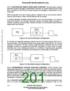
A resident debugger simplifies implementation of an in-circuit emulator. In a common
setup (see Figure 5-18), emulator hardware replaces the target system processor. A
complex, expensive pod-and-cable interface provides a communication path between
target system and emulator.
IN-CIRCUIT
EMULATOR
TARGET
TARGET
MCU
..
SYSTEM
.
Figure 5-18. In-Circuit Emulator Configuration
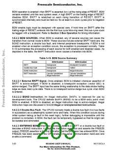
By contrast, an integrated debugger supports use of a bus state analyzer (BSA) for in-
circuit emulation. The processor remains in the target system (see Figure 5-19), and the
interface is simplified. The BSA monitors target processor operation and the on-chip
debugger controls the operating environment. Emulation is much closer to target
hardware; thus, many interfacing problems (i.e., limitations on high-frequency operation,
AC and DC parametric mismatches, and restrictions on cable length) are minimized.
TARGET
SYSTEM
BUS STATE
TARGET
.
MCU
Figure 5-19. Bus State Analyzer Configuration
5.6.1.2 DETERMINISTIC OPCODE TRACKING OVERVIEW. CPU32 function code
outputs are augmented by two supplementary signals that monitor the instruction pipeline.
The IFETCH output signal identifies bus cycles in which data is loaded into the pipeline
and signals pipeline flushes. The IPIPE output signal indicates when each mid-instruction
pipeline advance occurs and when instruction execution begins. These signals allow a
BSA to synchronize with instruction stream activity. Refer to 5.6.3 Deterministic Opcode
Tracking for complete information.
5.6.1.3 ON-CHIP HARDWARE BREAKPOINT OVERVIEW. An external breakpoint input
and an on-chip hardware breakpoint capability permit breakpoint trap on any
5- 64
MC68340 USER’S MANUAL
MOTOROLA
For More Information On This Product,
Go to: www.freescale.com

 FREESCALE [ Freescale ]