Freescale Semiconductor, Inc.
Bus operation in progress at the time of a fault is conveyed by the SSW.
15
14
13
0
12
11
10
9
8
7
6
5
4
3
2
1
0
TP
MV
TR
B1
B0
RR
RM
IN
RW
LG
SIZ
FUNC
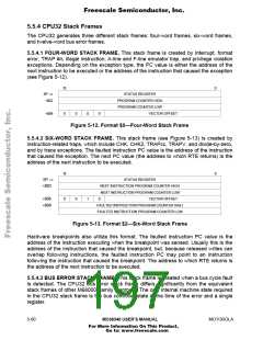
The bus error stack frame is 12 words in length. There are three variations of the frame,
each distinguished by different values in the SSW TP and MV fields.
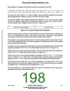
An internal transfer count register appears at location SP + $14 in all bus error stack
frames. The register contains an 8-bit microcode revision number, and, for type III faults,
an 8-bit transfer count. Register format is shown in Figure 5-14.
15
8
7
0
MICROCODE REVISION NUMBER
TRANSFER COUNT
Figure 5-14. Internal Transfer Count Register
The microcode revision number is checked before a bus error stack frame is restored via
RTE. In a multiprocessor system, this check ensures that a processor using stacked
information is at the same revision level as the processor that created it.
The transfer count is ignored unless the MV bit in the stacked SSW is set. If the MV bit is
set, the least significant byte of the internal register is reloaded into the MOVEM transfer
counter during RTE execution.
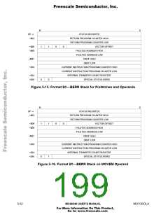
For faults occurring during normal instruction execution (both prefetches and non-MOVEM
operand accesses) SSW TP, MV = 00. Stack frame format is shown in Figure 5-15.
Faults that occur during the operand portion of the MOVEM instruction are identified by
SSW TP, MV = 01. Stack frame format is shown in Figure 5-16.
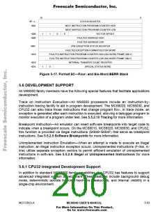
When a bus error occurs during exception processing, SSW TP, MV = 10. The frame
shown in Figure 5-17 is written below the faulting frame. Stacking begins at the address
pointed to by SP – 6 (SP value is the value before initial stacking on the faulted frame).
The frame can have either four or six words, depending on the type of error. Four-word
stack frames do not include the faulted instruction PC (the internal transfer count register
is located at SP + $10 and the SSW is located at SP + $12).
The fault address of a dynamically sized bus cycle is the address of the upper byte,
regardless of the byte that caused the error.
MOTOROLA
MC68340 USER’S MANUAL
5- 61
For More Information On This Product,
Go to: www.freescale.com

 FREESCALE [ Freescale ]