Freescale Semiconductor, Inc.
4.2.2.6.2 Using the Periodic Timer as a Real-Time Clock. The periodic interrupt timer
can be used as a real-time clock interrupt by setting it up to generate an interrupt with a
one-second period. Rearranging the periodic timer period equation to solve for the desired
count value:
PITR count value
PITR count value
PITR count value
=
=
=
(PIT period) (EXTAL frequency)
2
(Prescaler value) (2 )
(1) (32768)
2
(512) (2 )
16 (decimal)
Therefore, when using a 32.768-kHz crystal, the PITR should be loaded with a value of
$10 with the prescaler enabled to generate interrupts at a one-second rate.
4.2.2.7 SIMULTANEOUS INTERRUPTS BY SOURCES IN THE SIM40. If multiple
interrupt sources at the same interrupt level are simultaneously asserted in the SIM40, it
will prioritize and service the interrupts in the following order: 1) software watchdog, 2)
periodic interrupt timer, and 3) external interrupts.
4.2.3 Clock Synthesizer Operation
The clock synthesizer can operate with either an external crystal or an external oscillator
for reference, using the internal phase-locked loop (PLL) and voltage-controlled oscillator
(VCO), or an external clock can directly drive the clock signal at the operating frequency.
The four modes of clock operation are listed in Table 4-1.
Table 4-1. Clock Operating Modes
MODCK
Reset
Value
V
CCSYN
Operating
Value
Mode
Description
External crystal or oscillator used with the on-chip PLL and VCO to
generate a system clock and CLKOUT of programmable rates.
Crystal Mode
5 V
0 V
5 V
0 V
External Clock
The desired operating frequency is driven into EXTAL resulting in a
Mode without PLL system clock and CLKOUT of the same frequency, not tightly coupled.
The desired operating frequency is driven into EXTAL, resulting in a
system clock and CLKOUT of the same frequency, with a tight skew
between input and output signals.
External Clock
Mode with PLL
0 V
X
5 V
5 V
Upon input signal loss for either clock mode using the PLL, operation
continues at approximately one-half operating speed (affected by the
value of the X-bit in the SYNCR).
Limp Mode
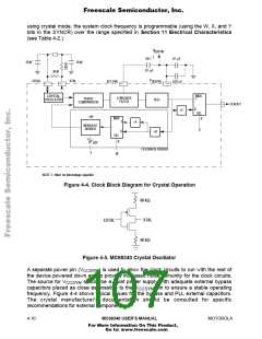
In crystal mode (see Figure 4-4), the clock synthesizer can operate from the on-chip PLL
and VCO, using a parallel resonant crystal connected between the EXTAL and XTAL pins,
or an external oscillator connected to EXTAL as a reference frequency source. The
oscillator circuit is shown in Figure 4-5. A 32.768-kHz watch crystal provides an
inexpensive reference, but the reference crystal or external oscillator frequency can be
any frequency in the range specified in Section 11 Electrical Characteristics. When
MOTOROLA
MC68340 USER’S MANUAL
4- 9
For More Information On This Product,
Go to: www.freescale.com

 FREESCALE [ Freescale ]