Freescale Semiconductor, Inc.
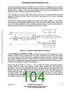
interrupt (as programmed by the SWRI bit in the SYPCR). The address of the interrupt
service routine for the software watchdog interrupt is stored in the software interrupt vector
register (SWIV). Figure 4-3 shows a block diagram of the software watchdog as well as
the clock control circuits for the periodic interrupt timer.
The watchdog clock rate is determined by the SWP bit in the periodic interrupt timer
register (PITR) and the SWT bits in the SYPCR. See Table 4-7 for a list of watchdog
timeout periods.
The software watchdog service sequence consists of the following steps: 1) write $55 to
the software service register (SWSR) and 2) write $AA to the SWSR. Both writes must
occur in the order listed prior to the watchdog timeout, but any number of instructions or
accesses to the SWSR can be executed between the two writes.
PITR
SWP
PTP
FREEZE
PITCLK
.
PIT
INTERRUPT
4
.
MODULUS COUNTER
CLOCK
MUX
CLOCK
DISABLE
9
EXTAL
PRESCALER (2 )
PRECLK
RESET
SWCLK
15
15 STAGE DIVIDER CHAIN (2
)
LPSTOP
13
9
15
11
2
2
2
2
Figure 4-3. Software Watchdog Block Diagram
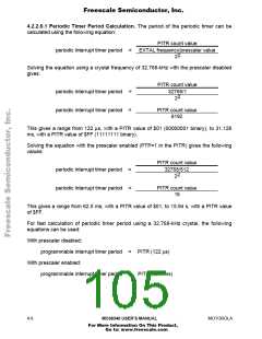
4.2.2.6 PERIODIC INTERRUPT TIMER. The periodic interrupt timer consists of an 8-bit
modulus counter that is loaded with the value contained in the PITR (see Figure
4-3). The modulus counter is clocked by a signal derived from the EXTAL input pin unless
an external frequency source is used. When an external frequency source is used
(MODCK low during reset), the default state of the prescaler control bits (SWP and PTP)
in the PITR is changed to enable both prescalers.
Either clock source (EXTAL or EXTAL ÷ 512) is divided by 4 before driving the modulus
counter (PITCLK). When the modulus counter value reaches zero, an interrupt is
generated. The level of the generated interrupt is programmed into the PIRQL bits in the
periodic interrupt control register (PICR). During the IACK cycle, the SIM40 places the
periodic interrupt vector, programmed into the PIV bits in the PICR, onto the internal bus.
The value of bits 7–0 in the PITR is then loaded again into the modulus counter, and the
counting process starts over. If a new value is written to the PITR, this value is loaded into
the modulus counter when the current count is completed.
MOTOROLA
MC68340 USER’S MANUAL
4- 7
For More Information On This Product,
Go to: www.freescale.com

 FREESCALE [ Freescale ]