Freescale Semiconductor, Inc.
MSCAN Controller
Clock System
The above parameters can be set by programming the bus timing
registers (CBTR0–1, see msCAN12 Bus Timing Register 0 (CBTR0) and
msCAN12 Bus Timing Register 1 (CBTR1)).
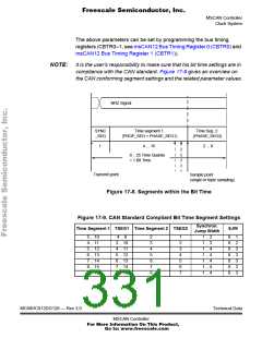
NOTE: It is the user’s responsibility to make sure that his bit time settings are in
compliance with the CAN standard. Figure 17-9 gives an overview on
the CAN conforming segment settings and the related parameter values.
NRZ Signal
SYNC
_SEG
Time segment 1
(PROP_SEG + PHASE_SEG1)
Time Seg. 2
(PHASE_SEG2)
1
4 ... 16
2 ... 8
8... 25 Time Quanta
= 1 Bit Time
Transmit point
Sample point
(single or triple sampling)
Figure 17-8. Segments within the Bit Time
Figure 17-9. CAN Standard Compliant Bit Time Segment Settings
Synchron.
Jump Width
Time Segment 1 TSEG1 Time Segment 2 TSEG2
SJW
5 .. 10
4 .. 11
5 .. 12
6 .. 13
7 .. 14
8 .. 15
9 .. 16
4 .. 9
3 .. 10
4 .. 11
5 .. 12
6 .. 13
7 .. 14
8 .. 15
2
3
4
5
6
7
8
1
2
3
4
5
6
7
1 .. 2
0 .. 1
0 .. 2
0 .. 3
0 .. 3
0 .. 3
0 .. 3
0 .. 3
1 .. 3
1 .. 4
1 .. 4
1 .. 4
1 .. 4
1 .. 4
MC68HC912DG128 — Rev 3.0
Technical Data
MSCAN Controller
For More Information On This Product,
Go to: www.freescale.com

 FREESCALE [ Freescale ]