Resets
default behavior of Stop mode. By asserting a peripheral’s Stop disable bit, the peripheral clock continues
to operate in Stop mode. This is useful to generate interrupts which will recover the device from Stop mode
to Run mode. Standby mode provides normal operation but at very low speed and power utilization. It is
possible to invoke Stop or Wait mode while in Standby mode for even greater levels of power reduction.
A 400kHz external clock can optionally be used in Standby mode to produce the required Standby 200kHz
system clock rate. Power-down mode, which selects the ROSC clock source but shuts it off, fully disables
the device and minimizes its power utilization but is only recoverable via reset.
When the PLL is not selected and the system bus is operating at 200kHz or less, the large regulator can be
put into its Standby mode (LRSTDBY) to reduce the power utilization of that regulator.
All peripherals, except the COP/watchdog timer, run at the system clock frequency or optional 3X system
2
clock for PWM, Timers, and I C. The COP timer runs at OSC_CLK / 1024. The maximum frequency of
operation is 32MHz.
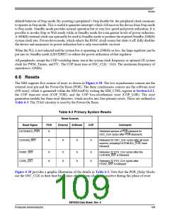
6.6 Resets
The SIM supports five sources of reset, as shown in Figure 6-28. The two asynchronous sources are the
external reset pin and the Power-On Reset (POR). The three synchronous sources are the software reset
(SW reset), which is generated within the SIM itself by writing the SIM_CTRL register in Section 6.3.1,
the COP time-out reset (COP_TOR), and the COP loss-of-reference reset (COP_LOR). The reset
generation module has three reset detectors, which resolve into four primary resets. These are outlined in
Table 6-3. The JTAG circuitry is reset by the Power-On Reset.
Table 6-3 Primary System Resets
Reset Sources
Reset Signal
POR
External
Software
COP
Comments
EXTENDED_POR
X
Stretched version of POR released 64
OSC_CLK cycles after POR deasserts
CLKGEN_RST
X
X
X
X
Released 32 OSC_CLK cycles after all reset
sources, including EXTENDED_POR, have
released
PERIP_RST
CORE_RST
X
X
X
X
X
X
X
X
Releases 32 SYS_CLK cycles after the
CLKGEN_RST is released
Releases 32 SYS_CLK cycles after
PERIP_RST is released
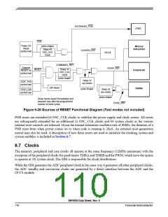
Figure 6-28 provides a graphic illustration of the details in Table 6-3. Note that the POR_Delay blocks
use the OSC_CLK as their time base, since other system clocks are inactive during this phase of reset.
56F8036 Data Sheet, Rev. 6
Freescale Semiconductor
109

 FREESCALE [ Freescale ]