Block Diagram
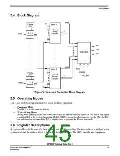
5.4 Block Diagram
any0
Priority
Level
Level 0
46 -> 6
Priority
Encoder
6
2 -> 4
INT0
Decode
INT
VAB
IPIC
CONTROL
any3
IACK
SR[9:8]
PIC_EN
Level 3
Priority
Level
46 -> 6
Priority
6
Encoder
2 -> 4
Decode
INT45
Figure 5-1 Interrupt Controller Block Diagram
5.5 Operating Modes
The ITCN module design contains two major modes of operation:
•
•
Functional Mode
The ITCN is in this mode by default.
Wait and Stop Modes
During Wait and Stop modes, the system clocks and the 56800E core are turned off. The ITCN will signal
a pending IRQ to the System Integration Module (SIM) to restart the clocks and service the IRQ. An IRQ
can only wake up the core if the IRQ is enabled prior to entering the Wait or Stop mode.
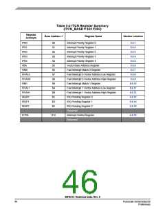
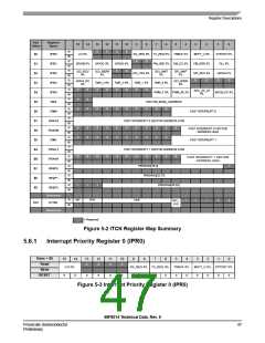
5.6 Register Descriptions
A register address is the sum of a base address and an address offset. The base address is defined at the
system level and the address offset is defined at the module level. The ITCN module has 16 registers.
56F8014 Technical Data, Rev. 9
Freescale Semiconductor
Preliminary
45

 FREESCALE [ Freescale ]