5.3.1
Normal Interrupt Handling
Once the INTC has determined that an interrupt is to be serviced and which interrupt has the highest
priority, an interrupt vector address is generated. Normal interrupt handling concatenates the Vector Base
Address (VBA) and the vector number to determine the vector address, generating an offset into the vector
table for each interrupt.
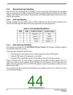
5.3.2
Interrupt Nesting
Interrupt exceptions may be nested to allow an IRQ of higher priority than the current exception to be
serviced. The following table defines the nesting requirements for each priority level.
Table 5-1 Interrupt Mask Bit Definition
Exceptions Permitted
Exceptions Masked
SR[9]
SR[8]
0
0
1
1
0
1
0
1
Priorities 0, 1, 2, 3
Priorities 1, 2, 3
Priorities 2, 3
Priority 3
None
Priority 0
Priorities 0, 1
Priorities 0, 1, 2
5.3.3
Fast Interrupt Handling
Fast interrupts are described in the DSP56800E Reference Manual. The interrupt controller recognizes
Fast Interrupts before the core does.
A Fast Interrupt is defined (to the ITCN) by:
1. Setting the priority of the interrupt as level 2, with the appropriate field in the IPR registers
2. Setting the FIMn register to the appropriate vector number
3. Setting the FIVALn and FIVAHn registers with the address of the code for the Fast Interrupt
When an interrupt occurs, its vector number is compared with the FIM0 and FIM1 register values. If a
match occurs, and it is a level 2 interrupt, the ITCN handles it as a Fast Interrupt. The ITCN takes the vector
address from the appropriate FIVALn and FIVAHn registers, instead of generating an address that is an
offset from the VBA.
The core then fetches the instruction from the indicated vector adddress and if it is not a JSR, the core starts
its Fast Interrupt handling.
56F8014 Technical Data, Rev. 9
44
Freescale Semiconductor
Preliminary

 FREESCALE [ Freescale ]