F71872
99
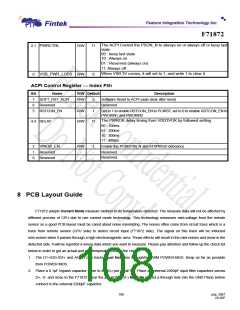
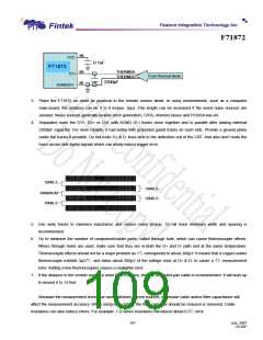
VCC
0.1uF
F71872
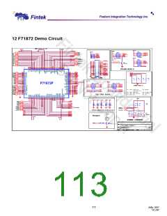
F71872F
89
86
THERMDA
THERMDC
D1+
From thermal diode
2200pF
AGND(D-)
3. Place the F71872 as close as practical to the remote sensor diode. In noisy environments, such as a computer
main-board, the distance can be 4 to 8 inches. (typ). This length can be increased if the worst noise sources are
avoided. Noise sources generally include clock generators, CRTs, memory buses and PCI/ISA bus etc.
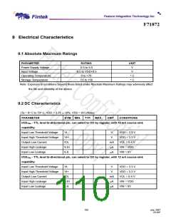
4. Separated route the D1+, D2+ or D3+ with AGND (D-) tracks close together and in parallel after adding external
2200pF capacitor. For more reliable, it had better with grounded guard tracks on each side. Provide a ground plane
under the tracks if possible. Do not route D+ & D- lines next to the deflection coil of the CRT. And also don’t route the
trace across fast digital signals which can easily induce bigger error.
GND
10MILS
THERMDA(DXP)
10MILS
MINIMUM
THERMDC(DXN)
10MILS
10MILS
GND
5. Use wide tracks to minimize inductance and reduce noise pickup. 10 mil track minimum width and spacing is
recommended.
6. Try to minimize the number of component/solder joints, called through hole, which can cause thermocouple effects.
Where through holes are used, make sure that they are in both the D+ and D- path and at the same temperature.
Thermocouple effects should not be a major problem as 1℃corresponds to about 200µV. It means that a copper-solder
thermocouple exhibits 3µV/℃, and takes about 200µV of the voltage error at D+ & D- to cause a 1℃ measurement
error. Adding a few thermocouples causes a negligible error.
7. If the distance to the remote sensor is more than 8 inches, the use of twisted pair cable is recommended. It will work up
to around 6 to 12 feet.
Because the measurement technique uses switched current sources, excessive cable and/or filter capacitance will
affect the measurement accuracy. When using long cables, the filter capacitor should be reduced or removed. Cable
resistance can also induce errors. For example: 1 Ω series resistance introduces about 0.5℃error.
107
July, 2007
V0.28P

 FINTEK [ FEATURE INTEGRATION TECHNOLOGY INC. ]