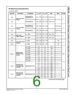
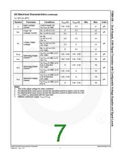
DC Electrical Characteristics (Continued)
TA=-40°C to +85°C.
Symbol
Parameter
Conditions
VCCA (V)
VCCB (V)
Min.
Max.
Units
Input Leakage
Current
Control Inputs /OE
VIN=VCCA or GND
II
1.65 - 5.50
5.5
µA
±1
An, VO=0V to 5.5V
Bn, VO=0V to 5.5V
0
5.5
0
±2
±2
Power Off
Leakage Current
IOFF
µA
µA
5.5
An, Bn
VO=0V or 5.5V,
/OE VIH
5.5
5.5
±5
3-State Output
Leakage
IOZ
An, VO=0V or 5.5V,
/OE=GND
5.5
0
0
±5
±5
10
10
Bn, VO=0V or 5.5V,
/OE=GND
5.5
VIN=VCCI or GND, IO=0
/OE=GND
ICCA/B
ICCZ
1.65 - 5.50 1.65 - 5.50
1.65 - 5.50 1.65 - 5.50
µA
µA
Quiescent Supply
Current( 6,7)
VIN=VCCI or GND, IO=0
/OE=VIH
VIN=VCCB or GND, IO=0
B-to-A Direction
/OE=GND
0
1.65 - 5.50
-10
10
Quiescent Supply
Current( 6,7)
ICCA
µA
µA
VIN=VCCA or GND, IO=0
A-to-B
1.65 - 5.50
1.65 - 5.50
0
0
0
VIN=VCCA or GND, IO=0
A-to-B Direction
/OE=GND
-10
10
Quiescent Supply
Current
ICCB
VIN=VCCB or GND, IO=0
B-to-A
1.65 - 5.50
Notes:
3. This is the output voltage for static conditions.
4. An external driver must source at least the specified current to switch LOW-to-HIGH.
5. An external driver must source at least the specified current to switch HIGH-to-LOW.
6.
VCCI is the VCC associated with the input side.
7. Reflects current per supply, VCCA or VCCB
.
© 2010 Fairchild Semiconductor Corporation
FXMA108 • Rev. 1.0.1
www.fairchildsemi.com
7

 FAIRCHILD [ FAIRCHILD SEMICONDUCTOR ]