XRT86L30
REV. 1.0.1
SINGLE T1/E1/J1 FRAMER/LIU COMBO
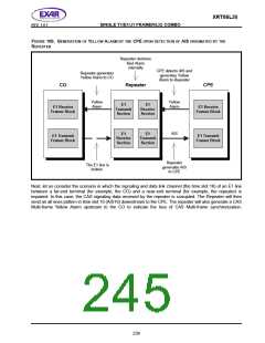
Upon detection of Loss of Signal (LOS) or Loss of Frame (LOF) condition, the receiver will transmit the Yellow
Alarm back to the source indicating the loss of an incoming signal. This Yellow Alarm informs the source that
there is a problem further down the line and its transmission is not being received at the destination.
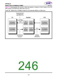
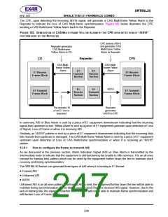
On the other hand, upon detection of Loss of CAS Multi-frame alignment pattern, the receiver section of the
XRT86L30 framer will transmit a CAS Multi-frame Yellow Alarm back to the source indicating the Loss of CAS
Multi-frame synchronization.
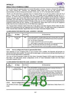
The Yellow Alarm Generation Select bits of the Alarm Generation Register (AGR) enable transmission of
different types of Yellow alarm that are supported by the XRT86L30 framer.
12.5.4
Transmit Yellow Alarm
The Yellow Alarm bits are located at bit 2 of time slot 0 of non-FAS frames. A logic one of this bit denotes the
Yellow Alarm and a logic zero of this bit denotes normal operation. The XRT86L30 supports transmission of
Yellow Alarm automatically or manually.
When the Yellow Alarm Generation Select bits of the Alarm Generation Register are set to 01, the Yellow Alarm
bit is transmitted by echoing the received FAS alignment pattern. If the correct FAS alignment is received, the
Yellow Alarm bit is set to zero. If the FAS alignment pattern is missing or corrupted, the Yellow Alarm bit is set
to one while Loss of Frame Synchronization is declared.
When the Yellow Alarm Generation Select bits of the Alarm Generation Register are set to 10, the Yellow Alarm
bit is transmitted as zero.
When the Yellow Alarm Generation Select bits of the Alarm Generation Register are set to 11, the Yellow Alarm
bit is transmitted as one.
12.5.5
Transmit CAS Multi-frame Yellow Alarm
Within the sixteen-frame CAS Multi-frame, the CAS Multi-frame Yellow Alarm bits are located at bit 6 of time
slot 16 of frame number 0. A logic one of this bit denotes the CAS Multi-frame Yellow Alarm and a logic zero of
this bit denotes normal operation. The XRT86L30 supports transmission of CAS Multi-frame Yellow Alarm
automatically or manually.
When the CAS Multi-frame Yellow Alarm Generation Select bits of the Alarm Generation Register are set to 01,
the CAS Multi-frame Yellow Alarm bit is transmitted by echoing the received CAS Multi-frame alignment pattern
(the four zeros pattern). If the correct CAS Multi-frame alignment is received, the CAS Multi-frame Yellow
Alarm bit is set to zero. If the CAS Multi-frame alignment pattern is missing or corrupted, the CAS Multi-frame
Yellow Alarm bit is set to one while Loss of CAS Multi-frame Synchronization is declared.
When the CAS Multi-frame Yellow Alarm Generation Select bits of the Alarm Generation Register are set to 10,
the CAS Multi-frame Yellow Alarm bit is transmitted as zero.
When the CAS Multi-frame Yellow Alarm Generation Select bits of the Alarm Generation Register are set to 11,
the CAS Multi-frame Yellow Alarm bit is transmitted as one.
238

 EXAR [ EXAR CORPORATION ]