XRT86L30
SINGLE T1/E1/J1 FRAMER/LIU COMBO
REV. 1.0.1
6.8
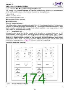
Transmit SLC®96 Data link Controller
The SLC®96 T1 format is invented by AT&T and is used between the Digital Switch and a SLC®96 formatted
remote terminal. The purpose of the SLC®96 product is to provide standard telephone service or Plain Old
Telephone Service (POTS) in areas of high subscriber density but back-haul the traffic over T1 facilities.
To support the SLC®96 formatted remote terminal equipment, which is likely in an underground location, the
T1 framer must:
•
•
•
•
Indicate equipment failures of the equipment to maintenance personal
Indicate failures of the POTS lines
Test the POTS lines
Provide redundancy on the T1s
The SLC®96 framing format is a D4 Super-frame (SF) format with specialized data link information bits. These
data link information bits take the position of the Super-frame Alignment (Fs) bit positions. These bits consist of
the following.
•
•
•
•
•
•
•
Concentrator bits (C, bit position 1 to 11)
First Spoiler bits (FS, bit position 12 to 14)
Maintenance bits (M, bit position 15 to 17)
Alarm bits (A, bit position 18 to 19)
Protection Line Switch bits (S, bit position 20 to 23)
Second Spoiler bit (SS, bit position 24)
Resynchronization pattern (000111000111)
In SLC®96 mode, a six 6-bit datalink message will generate a one 9-ms frame of the SLC®96 message
format. The format of the datalink message is given in BELLCORE TR-TSY-000008. When SLC®96 mode is
enabled, the Fs bit is replaced by the data link message read from memory at the beginning of each D4 super-
frame. The XRT86L30 allocates two 6-byte buffers to provide the SLC®96 Data Link Controller an alternating
access mechanism for information transmission. The bit ordering and usage is shown in the following table;
and the LSB is sent first. Note that these registers are memory-based storage and they need to be initialized.
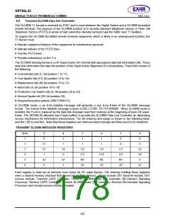
TRANSMIT SLC®96 MESSAGE REGISTERS
B
YTE
1
5
0
4
1
3
1
2
1
1
0
0
0
2
C1
C7
1
1
1
1
0
0
3
C6
0
C5
C11
M3
S4
C4
C10
M2
S3
C3
C9
M1
S2
C2
C8
0
4
5
A2
0
A1
1
6
S1
Each register is read out of memory once every six SF super-frames. The memory holding these registers
owns a shared memory structure that is used by multiple devices. These include DS1 transmit module, DS1
receive module, Transmit LAPD Controller, Transmit SLC®96 Data Link controller, Bit-Oriented Signaling
Processor, Receive LAPD Controller, Receive SLC®96 Data Link Controller, Receive Bit-Oriented Signaling
Processor and microprocessor interface module.
167

 EXAR [ EXAR CORPORATION ]