XRT86L30
SINGLE T1/E1/J1 FRAMER/LIU COMBO
REV. 1.0.1
of the next frame, in some applications. However, all receivers must be able to accommodate receipt of one or
more consecutive flags.
6.7.7
Address Field
The address field consists of two octets. A single octet address field is reserved for LAPB operation in order to
allow a single LAPB data link connection to be multiplexed along with LAPD data link connections.
6.7.8
Address Field Extension bit (EA)
The address field range is extended by reserving bit 1 of the address field octets to indicate the final octet of
the address field. The presence of a 1 in bit 1 of an address field octet signals that it is the final octet of the
address field. The double octet address field for LAPD operation shall have bit 1 of the first octet set to a 0 and
bit 1 of the second octet set to 1.
6.7.9
Command or Response bit (C/R)
The Command or Response bit identifies a frame as either a command or a response. The user side shall
send commands with the C/R bit set to 0, and responses with the C/R bit set to 1. The network side shall do the
opposite; That is, commands are sent with C/R bit set to 1, and responses are sent with C/R bit set to 0.
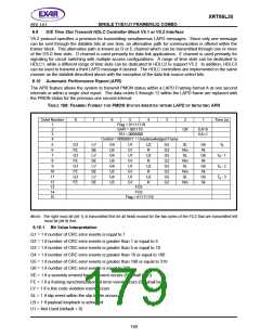
6.7.10 Service Access Point Identifier (SAPI)
The Service Access Point Identifier identifies a point at which data link layer services are preceded by a data
link layer entity type to a layer 3 or management entity. Consequently, the SAPI specifies a data link layer entity
type that should process a data link layer frame and also a layer 3 or management entity, which is to receive
information carried by the data link layer frame. The SAPI allows 64 service access points to be specified,
where bit 3 of the address field octet containing the SAPI is the least significant binary digit and bit 8 is the most
significant. SAPI values are 0x14 and 0x15 for performance report message and path or test signal
identification message respectively.
6.7.11 Terminal Endpoint Identifier (TEI)
The TEI sub-field allows 128 values where bit 2 of the address field octet containing the TEI is the least
significant binary digit and bit 8 is the most significant binary digit. The TEI sub-field bit pattern 111 1111 (=127)
is defined as the group TEI. The group TEI is assigned permanently to the broadcast data link connection
associated with the addressed Service Access Point (SAP). TEI values other than 127 are used for the point-
to-point data link connections associated with the addressed SAP. Non-automatic TEI values (0-63) are
selected by the user, and their allocation is the responsibility of the user. The network automatically selects
and allocates TEI values (64-126).
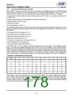
6.7.12 Control Field
The control field identifies the type of frame which will be either a command or response. The control field shall
consist of one or two octets. Three types of control field formats are specified: 2-octet numbered information
transfer (I format), 2-octet supervisory functions (S format), and single-octet unnumbered information transfers
and control functions (U format). The control field for T1/E1 message is categorized as a single-octet
unacknowledged information transfer having the value 0x03.
6.7.13 Frame Check Sequence (FCS) Field
The source of either the performance report or an identification message shall generate the frame check
sequence. The FCS field shall be a 16-bit sequence. It shall be the ones complement of the sum (modulo 2)
of:
•
•
The remainder of xk (x15 + x14 + x13 + x12 + x11 + x10 + x9 + x8 + x7 + x6 + x5 + x4 + x3 + x2 + x + 1)
divided (modulo 2) by the generator polynomial x16 + x12 + x5 + 1, where k is the number of bits in the frame
existing between, but not including, the final bit of the opening flag and the first bit of the FCS, excluding bits
inserted for transparency, and
The remainder of the division (modulo 2) by the generator polynomial x16 + x12 + x5 + 1, of the product of
x16 by the content of the frame existing between, but not including, the final bit of the opening flag and the
first bit of the FCS, excluding bits inserted for transparency.
As a typical implementation at the transmitter, the initial content of the register of the device computing the
remainder of the division is preset to all 1s and is then modified by division by the generator polynomial on the
165

 EXAR [ EXAR CORPORATION ]