áç
ST16C650A
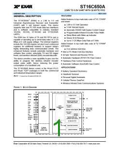
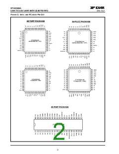
2.90V TO 5.5V UART WITH 32-BYTE FIFO
REV. 5.0.0
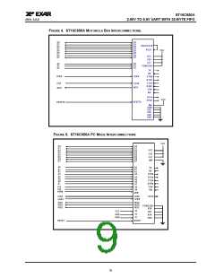
40-
44-
48-
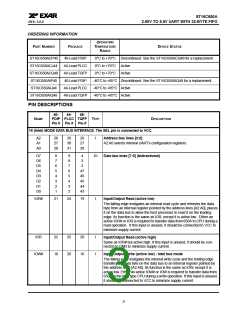
NAME
PDIP PLCC TQFP TYPE
DESCRIPTION
PIN #
PIN #
PIN #
AEN#
-
28
24
I
I
Address Enable input (active low)
When AEN# transition to logic 0, it decodes and validates COM 1-4 ports
address per S1, S2 and S3 inputs.
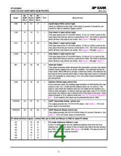
S1
S2
S3
-
-
-
23
10
35
21
5
Select 1 to 3
These are the standard PC COM 1-4 ports and IRQ selection inputs. See
Table 1 and Table 3 for details. The S1 pin has an internal 100kΩ pull-up
resistor.
31
IRQA
IRQB
IRQC
-
-
-
33
32
27
30
29
23
O
Interrupt Request A, B and C Outputs (active high, tri-state)
These are the interrupt outputs associated with COM 1-4 to be connected
to the host data bus. See interrupt section for details. The Interrupt
Requests A, B or C functions as IRQx to the PC bus. IRQx is enabled by
setting MCR bit-3 to logic 1 and the desired interrupt(s) in the interrupt
enable register (IER).
LPT1#
LPT2#
-
-
17
26
12
22
O
O
Line Printer Port-1 Decode Logic Output (active low)
This pin functions as the PC standard LPT-1 printer port address decode
logic output, see Table 1. The baud rate generator clock output, BAUD-
OUT#, is internally connected to the RCLK input in the PC mode.
Line Printer Port-2 Decode Logic Output (active low)
This pin functions as the PC standard LPT-2 printer port address decode
logic output, see Table 1.
MODEM OR SERIAL I/O INTERFACE
TX
RX
11
10
13
11
8
7
O
Transmit Data or wireless infrared transmit data
This output is active low in normal standard serial interface operation (RS-
232, RS-422 or RS-485) and active high in the infrared mode. Infrared
mode can be enabled by connecting pin ENIR to VCC or through software
setting after power up.
I
Receive Data or wireless infrared receive data
Normal received data input idles at logic 1 condition and logic 0 in the
infrared mode. The wireless infrared pulses are applied to the decoder.
This input must be connected to its idle logic state in either normal, logic 1,
or infrared mode, logic 0, else the receiver may report “receive break” and/
or “error” condition(s).
RTS#
CTS#
32
36
36
40
32
38
O
Request to Send or general purpose output (active low)
This port may be used for one of two functions:
1) automatic hardware flow control, see EFR bit-6, MCR bit-1and IER bit-
6.
2) RS485 half-duplex direction control, see XFR bits 2 and 5.
RTS# output must be asserted before auto RTS flow control can start.
I
Clear to Send or general purpose input (active low)
If used for automatic hardware flow control, data transmission will be
stopped when this pin is de-asserted and will resume when this pin is
asserted again. See EFR bit-7 and IER bit-7.
DTR#
DSR#
33
37
37
41
33
39
O
I
Data Terminal Ready or general purpose output (active low)
Data Set Ready input or general purpose input (active low)
5

 EXAR [ EXAR CORPORATION ]