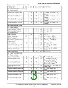
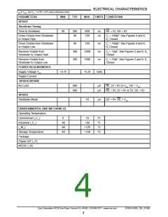
ELECTRICAL CHARACTERISTICS
TMIN to TMAX and VCC = +5.0V +/-5% unless otherwise noted.
PARAMETERS
MIN.
TYP.
MAX.
UNITS CONDITIONS
SP481E/SP485E DRIVER (continued)
AC Characteristics
Driver Enable to Output High
40
40
40
40
70
70
70
70
ns
ns
ns
ns
CL = 100pF, see Figures 4 and 6,
S2 closed
Driver Enable to Output Low
Driver Disable Time from High
Driver Disable Time from Low
CL = 100pF, see Figures 4 and 6,
Sꢀ closed
CL = 100pF, see Figures 4 and 6,
S2 closed
CL = 100pF, see Figures 4 and 6,
Sꢀ closed
SP481E/SP485E RECEIVER
DC Characteristics
Differential Input Threshold
-0.2
+0.2
+0.4
Volts -7V ≤ VCM ≤ +12V
Volts -7V ≤ VCM ≤ +12V
Differential Input Threshold
-0.4
(SP485EMN ONLY)
Input Hysteresis
20
ꢀ5
mV
VCM = 0V
Output Voltage High
Output Voltage Low
3.5
Volts IO = -4mA, VID = +200mV
Volts IO = +4mA, VID = +200mV
0.4
Three-State ( High Impedance)
Output Current
+/-ꢀ
µA
0.4V ≤ VO ≤ 2.4V; RE = 5V
Input Resistance
ꢀ2
kΩ
-7V ≤ VCM ≤ +12V
Input Current (A, B); VIN = ꢀ2V
+ꢀ.0
-0.8
95
mA
DE = 0V, VCC = 0V or 5.25V,
VIN = ꢀ2V
Input Current (A, B); VIN = -7V
mA
mA
DE = 0V, VCC = 0V or 5.25V,
VIN = -7V
Short Circuit Current
7
0V ≤ VO ≤ VCC
SP481E/SP485E RECEIVER
AC Characteristics
Max. Transmission Rate
Receiver Input to Output
ꢀ0
20
Mbps RE = 0V, DE = 0V
45
45
ꢀ3
45
45
45
45
ꢀ00
ꢀ00
ns
ns
ns
ns
ns
ns
ns
tPLH ; See Figures 3 & 7, RDIFF
54Ω, CLꢀ = CL2 = ꢀ00pF
=
=
Receiver Input to Output
Differential Receiver Skew
20
tPHL ; See Figures 3 & 7, RDIFF
54Ω, CLꢀ = CL2 = ꢀ00pF
RDIFF = 54Ω, CLꢀ = CL2 = 100pF, see
Figures 3 and 7
|tPHL - tPLH
|
Receiver Enable to Output Low
Receiver Enable to Output High
Receiver Disable from LOW
Receiver Disable from High
70
70
70
70
CRL = 15pF, Figures 2 & 8; Sꢀ
Closed
CRL = 15pF, Figures 2 & 8; S2
Closed
CRL = 15pF, Figures 2 & 8; Sꢀ
Closed
CRL = 15pF, Figures 2 & 8; S2
Closed
Exar Corporation 48720 Kato Road, Fremont CA, 94538 • 5ꢀ0-668-70ꢀ7 • www.exar.com
SP48ꢀE,485E_ꢀ00_ꢀ2ꢀ808
3

 EXAR [ EXAR CORPORATION ]