With the Air Discharge Method, an ESD
voltage is applied to the equipment under
test (EUT) through air. This simulates an
electricallychargedpersonreadytoconnect
a cable onto the rear of the system only to
findanunpleasantzapjustbeforetheperson
touches the back panel. The high energy
potential on the person discharges through
anarcingpathtotherearpanelofthesystem
before he or she even touches the system.
This energy, whether discharged directly or
throughair,ispredominantlyafunctionofthe
discharge current rather than the discharge
voltage. Variableswithanairdischargesuch
asapproachspeedoftheobjectcarryingthe
ESD potential to the system and humidity
will tend to change the discharge current.
For example, the rise time of the discharge
current varies with the approach speed.
30A
15A
0A
t = 0ns
t = 30ns
t →
Figure 11. ESD Test Waveform for IEC1000-4-2
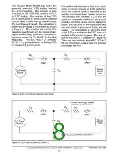
The voltage stored in the capacitor is then
applied through RS, the current limiting
resistor, onto the device under test (DUT).
In ESD tests, the SW2 switch is pulsed so
that the device under test receives a dura-
tion of voltage.
The Contact Discharge Method applies the
ESDcurrentdirectlytotheEUT. Thismethod
was devised to reduce the unpredictability
of the ESD arc. The discharge current rise
time is constant since the energy is directly
transferred without the air-gap arc. In situ-
ations such as hand held systems, the ESD
charge can be directly discharged to the
equipment from a person already holding
the equipment. The current is transferred
on to the keypad or the serial port of the
equipment directly and then travels through
the PCB and finally to the IC.
For the Human Body Model, the current
limitingresistor(RS)andthesourcecapacitor
(CS) are 1.5kΩ an 100pF, respectively. For
IEC-1000-4-2, the current limiting resistor
(R ) and the source capacitor (CS) are 330Ω
anS150pF, respectively.
The higher CS value and lower R value in
the IEC1000-4-2 model are moreSstringent
than the Human Body Model. The larger
storage capacitor injects a higher voltage
to the test point when SW2 is switched on.
The lower current limiting resistor increases
the current charge onto the test point.
The circuit model in Figures 9 and 10 repre-
sent the typical ESD testing circuit used for
allthreemethods. TheCS isinitiallycharged
with the DC power supply when the first
switch (SW1) is on. Now that the capacitor
is charged, the second switch (SW2) is on
while SW1 switches off.
SP48ꢀE, SP485E HUMAN BODY
IECꢀ000-4-2
FAMILY
MODEL
Air Discharge Direct Contact Level
Driver Outputs
Receiver Inputs
+/-ꢀ5kV
+/-ꢀ5kV
+/-ꢀ5kV
+/-ꢀ5kV
+/-8kV
+/-8kV
4
4
Exar Corporation 48720 Kato Road, Fremont CA, 94538 • 5ꢀ0-668-70ꢀ7 • www.exar.com
SP48ꢀE,485E_ꢀ00_ꢀ2ꢀ808
9

 EXAR [ EXAR CORPORATION ]