ZSPM1025A
True Digital PWM Controller (Single-Phase, Single-Rail)
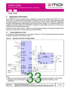
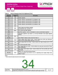
Table 5.1
Passive Component Values for the Application Circuit
Reference
Designator
Component
Value
Description
C1
C2
C3
C4
C5
C6
1.0µF
4.7µF
4.7µF
4.7µF
4.7µF
100nF
Ceramic capacitor.
Ceramic capacitor. Recommended 4.7µF, Minimum 1.0µF.
Ceramic capacitor. Recommended 4.7µF, Minimum 1.0µF.
Ceramic capacitor. Recommended 4.7µF, Minimum 1.0µF.
Ceramic capacitor. Recommended 4.7µF, Minimum 1.0µF.
Output voltage sense filtering capacitor.
Recommended 22pF, maximum 1 nF.
C7
22pF
C8
220nF*
DCR current-sense filter capacitor.
CIN
Input filter capacitors. Can be a combination of ceramic and electrolytic capacitors.
Output filter capacitors. See section 5.1.2 for more information on the output capacitor
selection.
COUT
R1
51Ω*
R2, R3
Select PMBus™ address resistor value from Table 4.2.
Output voltage divider bottom resistor. Connect between the VFBP and VFBN pins.
Select R4 for the output voltage range from 1.2V to 3.6V.
R4
1.0kΩ*
Output voltage divider top resistor. Connect between the output terminal and the VFBP
pin.
R5
R6
R7
1.74kΩ*
2.15kΩ*
9.1kΩ*
DCR current sense filter resistor.
Input voltage divider top resistor. Connect between the main power input and the VIN pin
of the ZSPM1025A.
Input voltage divider bottom resistor. Connect between the VIN and AGND pins of the
ZSPM1025A.
R8
1.0kΩ*
15kΩ*
PMBus™ SCL and SDA line pull-up resistors.
R9, R10
The pull-up resistors can be tied to 3.3V or 5V depending on the supply voltage of the
PMBus™ master.
Notes:
* Fixed component values that must not be changed.
© 2013 Zentrum Mikroelektronik Dresden AG — Rev. 1.00
All rights reserved. The material contained herein may not be reproduced, adapted, merged, translated, stored, or used without the
prior written consent of the copyright owner. The information furnished in this publication is subject to changes without notice.
Data Sheet
October 24, 2013
34 of 46

 ETC [ ETC ]