ZSPM1025A
True Digital PWM Controller (Single-Phase, Single-Rail)
5
Application Information
The ZSPM1025A has been designed and pre-configured to operate with the Murata OKLP-X/25-W12-C Power
Block, which is a complete point-of-load solution for 25A output currents. This section includes information about
the typical application circuit and recommended component values. ZMDI provides ZSPM1025A configuration
data that is downloadable from ZMDI website as part of the Pink Power Designer™ GUI. While the solution is pre-
configured, the design engineer has the flexibility to configure the output voltage and select one of the four pre-
defined and common output capacitor ranges.
Included in the Pink Power Designer™ software is a wizard dialog for guiding the user through the design process
step-by- step, which makes it a ready-made, easy and tested solution.
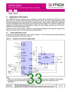
5.1. Typical Application Circuit
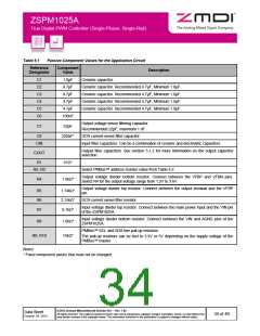
A schematic for the typical application circuit is shown in Figure 5.1. A list of recommended component values for
the passive components can be found in Table 5.1.
Figure 5.1
Application Circuit with a 5V Supply Voltage
+5V
VDD50
VDD33
VDD18
C1,C2,C3
Vin
+5V
GND
AVDD18
VREFP
R7
R8
VIN
+5V ENABLE
R1
ADCVREF
AGND
C4,C5,C6
+Vout
VIN
VOUT
GND
Murata
OKLP-X/25-W12-C
PWM
LSE
PWM
COUT
ADDR0
ADDR1
CIN
GND
PGND
R2,R3
TEMP +CS -CS
ON/OFF**
PGOOD
TEMP
GPIO0
C8
+3.3/5V*
CONTROL
PGOOD
ISNSP
ISNSN
R6
R9,R10
R5
SCL
VFBP
VFBN
PMBus™
R4
C7
SDA
Interface
SMBALERT
ZSPM1025A
Notes:
* PMBus™ SCL and SDA pull-up resistors R9/R10 can be tied to 3.3V or 5V depending on the PMBus™ master controller.
** The ON/OFF input can be active high or active low depending on the configuration of the CONTROL pin on the
ZSPM1025A.
© 2013 Zentrum Mikroelektronik Dresden AG — Rev. 1.00
All rights reserved. The material contained herein may not be reproduced, adapted, merged, translated, stored, or used without the
prior written consent of the copyright owner. The information furnished in this publication is subject to changes without notice.
Data Sheet
October 24, 2013
33 of 46

 ETC [ ETC ]