TLV9001, TLV9002, TLV9004
SBOS833A –OCTOBER 2017–REVISED DECEMBER 2017
www.ti.com
Typical Application (continued)
1
1
CF =
=
= 10.3 pF ö 10 pF
2ì pìRF ì f-3dB 2ì pì309 kWì50 kHz
(9)
The minimum op amp bandwidth required for this application is based on the value of RF, CF and the
capacitance on the IN– pin of the TLV9002 which is equal to the sum of the photodiode shunt capacitance, CPD,
the common-mode input capacitance CCM and the differential input capacitance CD as shown in Equation 10.
C
= CPD + CCM + CD = 47 pF+ 5 pF +1pF = 53 pF
IN
(10)
The minimum op amp bandwidth is calculated in Equation 11.
CIN + CF
f=BGW
í
í 324 kHz
2
2ì pìRF ì CF
(11)
The 1-MHz bandwidth of the TLV900x meets the minimum bandwidth requirement and remains stable in this
application configuration.
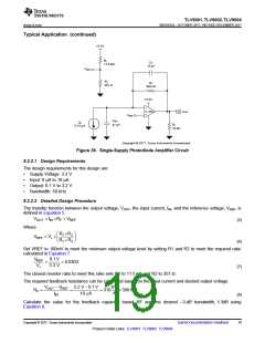
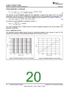
8.2.2.3 Application Curves
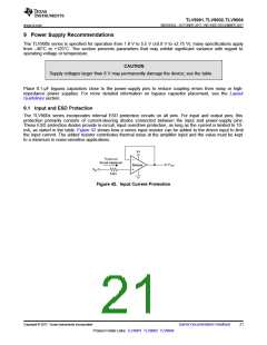
The measured current-to-voltage transfer function for photodiode amplifier circuit is shown in Figure 40. The
measured DC performance of the photodiode amplifier circuit is shown in Figure 41.
Figure 40. Photodiode Amplifier Circuit AC Gain Results
Figure 41. Photodiode Amplifier Circuit DC Results
20
Submit Documentation Feedback
Copyright © 2017, Texas Instruments Incorporated
Product Folder Links: TLV9001 TLV9002 TLV9004

 ETC [ ETC ]