Epson Research and Development
Page 15
Vancouver Design Center
4 MPC821 to S1D13506 Interface
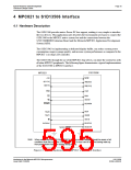
4.1 Hardware Description
The S1D13506 provides native Power PC bus support, making it very simple to interface
the two devices. This application note describes the environment necessary to connect the
S1D13506 to the MPC821 native system bus and the connections between the
S5U13506B00B Evaluation Board and the Motorola MPC821 Application Development
System (ADS).
The S1D13506, by implementing a dedicated display buffer, can reduce system power
consumption, improve image quality, and increase system performance as compared to the
MPC821’s on-chip LCD controller.
The S1D13506, through the use of the MPC821 chip selects, can share the system bus with
all other MPC821 peripherals. The following figure demonstrates a typical implementation
of the S1D13506 to MPC821 interface.
S1D13506
MPC821
M/R#
A10
A[11:31]
D[0:15]
AB[20:0]
DB[15:0]
CS4
TS
CS#
BS#
WAIT#
RD/WR#
TA
RD/WR
RD#
TSIZ0
TSIZ1
WE0#
BI
WE1#
BUSCLK
RESET#
SYSCLK
System
RESET
Note:
When connecting the S1D13506 RESET# pin, the system designer should be aware of all
conditions that may reset the S1D13506 (e.g. CPU reset can be asserted during wake-up
from power-down modes, or during debug states).
Figure 4-1: Typical Implementation of MPC821 to S1D13506 Interface
Interfacing to the Motorola MPC821 Microprocessor
Issue Date: 01/02/08
S1D13506
X25B-G-008-03

 EPSON [ EPSON COMPANY ]