Page 10
Epson Research and Development
Vancouver Design Center
The following table shows the Host Bus Interface options available. The Host Bus Interface
chosen will depend on the evaluation platform to be used.
Table 3-2: Host Bus Selection
MD11
MD3
MD2
MD1
Host Bus Interface
0
0
0
0
0
0
0
0
1
0
0
0
0
1
1
1
1
1
0
0
1
1
0
0
1
1
1
0
1
0
1
0
1
0
1
1
SH-4/SH-3
MC68K Bus 1
MC68K Bus 2
Generic
Reserved
MIPS/ISA
PowerPC
PC Card
Philips PR31500/PR31700 / Toshiba TX3912
= Required configuration when used in a PCI environment
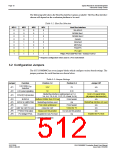
3.2 Configuration Jumpers
The S5U13506B00C has seven jumper blocks which configure various board settings. The
jumper positions for each function are shown below.
Table 3-3: Jumper Settings
Jumper
JP1
Function
Position 1-2
3.3V
Position 2-3
5V
Jumper Off
S1D13506 VDD
Selection
n/a
n/a
JP2
LCD panel signalling
5V
3.3V
MediaPlug interface (eight jumpers at 1-2,
3-4, 5-6, 7-8, 9-10, 11-12, 13-14 and 15-16)
16-bit LCD panel MSBs
(all jumpers disconnected)
JP3
FPDAT[15:8] function
JP4
JP5
JP6
JP7
JP8
JP9
BUSCLK
GPIO2 to VMPEPWR
CLKI
Buffered 33MHz from PCI bus
From header
n/a
n/a
MediaPlug interface used
From clock synthesizer
4.6mA for CRT
MediaPlug interface not used
From header
9.2mA for TV
Do not use this position
n/a
n/a
IREF for CRT/TV DAC
FPDAT[15:8] output
PCI bridge FPGA
n/a
n/a
Always use this position
Disabled for non-PCI host
Enabled for PCI host
= Default configuration
S1D13506
X25B-G-004-06
S5U13506B00C Evaluation Board User Manual
Issue Date: 01/02/06

 EPSON [ EPSON COMPANY ]