Epson Research and Development
Page 9
Vancouver Design Center
3 Installation and Configuration
The S5U13506B00C is designed to support as many platforms as possible. The
S5U13506B00C incorporates a DIP switch and several jumpers which allow both evalu-
ation board and S1D13506 LCD controller settings to be configured for a specified evalu-
ation platform.
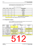
3.1 Configuration DIP Switches
The S1D13506 LCD controller has 16 configuration inputs (MD[15:0]) which are read on
the rising edge of RESET#. Where appropriate, the S5U13506B00C hard-wires some of
these configuration inputs, but in order to configure the S1D13506 for multiple host bus
interfaces a ten-position DIP switch is required. The following DIP switch settings
configure the S1D13506.
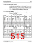
Table 3-1: Configuration DIP Switch Settings
value of this pin at rising edge of RESET# is used to configure:(1/0)
Switch Signal
Closed/On=1
Open/Off=0
S1-1
S1-2
S1-3
S1-4
S1-5
MD1
MD2
MD3
MD4
MD5
See Table 3-2:, “Host Bus Selection” on page 10
Little Endian
Big Endian
WAIT# is active high
WAIT# is active low
S1-6 MD10
S1-7 MD11
S1-8 MD12
Reserved. This switch must be in the closed position.
See Table 3-2:, “Host Bus Selection” on page 10
BUSCLK input divided by 2
BUSCLK input not divided
MD13: FPDAT[15:8] is MediaPlug interface;
external latches required for 16-bit STN panels.
MD13,
S1-9
MD13: support 16-bit STN panels directly.
MD14: MA11 is GPIO2.
MD14
MD14: MA11 is VMPEPWR.
WAIT# is always driven.
S1-10 MD15
WAIT# is tristated when S1D13506 is not selected.
= Required configuration when used in a PCI environment with MediaPlug disabled
Note
MD13 and MD14 are configured using the same switch, for further information see Sec-
tion 7, “Schematic Diagrams” on page 28.
S5U13506B00C Evaluation Board User Manual
Issue Date: 01/02/06
S1D13506
X25B-G-004-06

 EPSON [ EPSON COMPANY ]