Epson Research and Development
Page 173
Vancouver Design Center
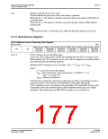
8.3.17 MediaPlug Register Descriptions
The S1D13506 has built-in support for Winnov’s MediaPlug connection designed for video
cameras. The following registers are used to control the connection and accept data from
the camera. The MediaPlug registers decode A11-A0 and require A20 = 0 and A12 = 1. The
MediaPlug registers are 16-bit wide. Byte access to the MediaPlug registers is not allowed.
For further information, see Section 17, “MediaPlug Interface” on page 212.
Note
The MediaPlug control registers must not be accessed while Power Save Mode is
enabled (REG[1F0h] bit 0 = 1).
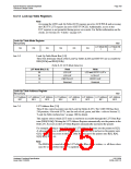
MediaPlug LCMD Register
REG[1000h]
RW
LCMD Bit 7
LCMD Bit 6
LCMD Bit 5
LCMD Bit 4
LCMD Bit 3
LCMD Bit 2
LCMD Bit 1
LCMD Bit 9
LCMD Bit 0
LCMD Bit 15 LCMD Bit 14 LCMD Bit 13 LCMD Bit 12 LCMD Bit 11 LCMD Bit 10
LCMD Bit 8
REG[1000h] bits 15-0 MediaPlug LCMD Bits [15:0]
A 16-bit register for setting and detecting various modes of operation of the MediaPlug
Local Slave. This register is handled differently for reads and writes. The following table
shows the MediaPlug description of the LCMD Register. See bit descriptions for details.
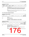
Table 8-37: MediaPlug LCMD Read/Write Descriptions
Data D15 D14 D13 D12 D11 D10
D9
Xxxxxxxxxx
Rev[3:0]
D8
D7
D6
D5
D4
D3
IC
IC
D2
MC
MC
D1
P
D0
W
Write
Read
TO[2:0]
TO[2:0]
00b
Rstat[2:0]
0b
P
W
bits 15-14
Timeout Option (MediaPlug Parameter TO)
These bits select the timeout delay in MediaPlug clock cycles:
Table 8-38: Timeout Option Delay
Timeout Option
Timeout (MediaPlug clock cycles)
Bits[15:14]
00
01
10
11
1023 (default)
64
128
64
bits 13-12
bits 11-8
A read from these bits will always return 00b.
A write to these bits has no hardware effect.
MediaPlug IC Revision (MediaPlug Parameter Rev)
The revision for this MediaPlug IC is “0011b”.
A write to these bits has no hardware effect.
Hardware Functional Specification
Issue Date: 01/02/06
S1D13506
X25B-A-001-10

 EPSON [ EPSON COMPANY ]