Page 172
Epson Research and Development
Vancouver Design Center
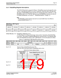
8.3.16 Common Display Mode Register
Display Mode Register
REG[1FCh]
RW
SwivelView™
Enable Bit 0
Display Mode Display Mode Display Mode
n/a
n/a
n/a
n/a
Select Bit 2
Select Bit 1
Select Bit 0
bit 6
SwivelView™ Enable Bit 0
When this bit = 1, the LCD display image is rotated 90° clockwise. Please refer to Section
15, “SwivelView™” on page 201 for application and limitations.
When this bit = 0, there is no hardware effect.
This bit in conjunction with SwivelView™ Enable Bit 1 achieves the following hardware
rotations.
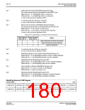
Table 8-35: Setting SwivelView Modes
SwivelView™ Modes
SwivelView Enable Bits
Normal
SwivelView 90°
SwivelView 180°
SwivelView 270°
SwivelView Enable Bit 0
(REG[1FCh] bit 6)
0
1
0
1
SwivelView Enable Bit 1
(REG[040h] bit 4)
0
0
1
1
bits 2-0
Display Mode Select Bits [2:0]
These bits select the display model according to the following table. The LCD display
mode is enabled/disabled using bit 0. Programming this bit from a 0 to a 1 starts the
power-on sequence. Programming this bit from a 1 to a 0 starts the power-off sequence.
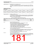
Table 8-36: Display Mode Selection
Display Mode Select Bits [2:0]
Display Mode Enabled
no display
000
001
010
011
100
101
110
111
LCD only
CRT only
EISD (CRT and LCD)
TV with flicker filter off
EISD (TV with flicker filter off and LCD)
TV with flicker filter on
EISD (TV with flicker filter on and LCD)
Note
REG[018h] bit 7 must be set to 1 when the flicker filter is enabled.
Note
The Flicker Filter reduces the “flickering” effect seen on interlaced displays by averag-
ing adjacent lines on the TV display. This “flickering” is caused by sharp vertical image
transitions that occur over one line (1 vertical pixel). For example, one pixel high lines,
edges of window boxes, etc. Flickering occurs because these high resolution lines are ef-
fectively displayed at half the refresh frequency due to interlacing.
S1D13506
X25B-A-001-10
Hardware Functional Specification
Issue Date: 01/02/06

 EPSON [ EPSON COMPANY ]