Preliminary EN29GL064
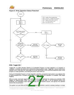
erase 2suspended. When the device is actively erasing (that is, the Embedded Erase algorithm is in
progress), DQ6 toggles. When the device enters the Erase Suspend mode, DQ6 stops toggling.
However, the system must also use DQ2 to determine which sectors are erasing or erase-suspended.
Alternatively, the system can use DQ7.
If a program address falls within a protected sector, DQ6 toggles for approximately 1ꢀs after the
program command sequence is written, then returns to reading array data. DQ6 also toggles during the
erase-suspend-program mode, and stops toggling once the Embedded Program Algorithm is complete.
Toggle Bit I on DQ6 requires either OE# or CE# to be de-asserted and reasserted to show the change in
state.
DQ2: Toggle Bit II
The “Toggle Bit II” on DQ2, when used with DQ6, indicates whether a particular sector is actively
erasing (that is, the Embedded Erase algorithm is in progress), or whether that sector is erase-
suspended. Toggle Bit II is valid after the rising edge of the final WE# pulse in the command sequence.
DQ2 toggles when the system reads at addresses within those sectors that have been selected for
erasure. But DQ2 cannot distinguish whether the sector is actively erasing or is erase-suspended. DQ6,
by comparison, indicates whether the device is actively erasing, or is in Erase Suspend, but cannot
distinguish which sectors are selected for erasure. Thus, both status bits are required for sector and
mode information.
Reading Toggle Bits DQ6/DQ2
Whenever the system initially begins reading toggle bit status, it must read DQ7–DQ0 at least twice in a
row to determine whether a toggle bit is toggling. Typically, the system would note and store the value of
the toggle bit after the first read. After the second read, the system would compare the new value of the
toggle bit with the first. If the toggle bit is not toggling, the device has completed the program or erases
operation. The system can read array data on DQ7–DQ0 on the following read cycle. However, if after
the initial two read cycles, the system determines that the toggle bit is still toggling, the system also
should note whether the value of DQ5 is high. If it is, the system should then determine again whether
the toggle bit is toggling, since the toggle bit may have stopped toggling just as DQ5 went high. If the
toggle bit is no longer toggling, the device has successfully completed the program or erases operation.
If it is still toggling, the device did not complete the operation successfully, and the system must write
the reset command to return to reading array data. The remaining scenario is that the system initially
determines that the toggle bit is toggling and DQ5 has not gone high. The system may continue to
monitor the toggle bit and DQ5 through successive read cycles, determining the status as described in
the previous paragraph. Alternatively, it may choose to perform other system tasks. In this case, the
system must start at the beginning of the algorithm when it returns to determine the status of the
operation.
Note
When verifying the status of a write operation (embedded program/erase) of a memory sector, DQ6 and
DQ2 toggle between high and low states in a series of consecutive and contiguous status read cycles. In
order for this toggling behavior to be properly observed, the consecutive status bit reads must not be
interleaved with read accesses to other memory sectors. If it is not possible to temporarily prevent reads
to other memory sectors, then it is recommended to use the DQ7 status bit as the alternative method of
determining the active or inactive status of the write operation.
DQ5: Exceeded Timing Limits
DQ5 indicates whether the program or erase time has exceeded a specified internal pulse count limit.
Under these conditions DQ5 produces a “1,” indicating that the program or erase cycle was not
successfully completed. The device does not output a 1 on DQ5 if the system tries to program a 1 to a
location that was previously programmed to 0. Only an erase operation can change a 0 back to a 1.
Under this condition, the device ignores the bit that was incorrectly instructed to be programmed from a
0 to a 1, while any other bits that were correctly requested to be changed from 1 to 0 are programmed.
Attempting to program a 0 to a 1 is masked during the programming operation. Under valid DQ5
conditions, the system must write the reset command to return to the read mode (or to the erase-
suspend-read mode if a sector was previously in the erase-suspend-program mode).
This Data Sheet may be revised by subsequent versions
or modifications due to changes in technical specifications.
©2004 Eon Silicon Solution, Inc., www.eonssi.com
28
Rev. A, Issue Date: 2009/3/20

 EON [ EON SILICON SOLUTION INC. ]