EM78P258N
8-Bit Microprocessor with OTP ROM
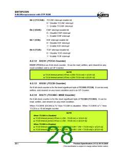
6.2.15 IOC81 (TCCC Counter)
IOC81 (TCCC) is an 8-bit clock counter that can be extended to 16-bit counter. It can
be read, written, and cleared on any reset condition.
If HF (Bit 2 of IOCA0) = 1 and IRE (Bit 3 of IOCA0) = 1, TCCC counter scale uses the
low-time segments of the pulse generated by Fcarrier frequency modulation (see Fig.
6-11 in Section 6.8.2, Function Description). Then TCCC value will be TCCC predict
value.
When HP = 0 or IRE = 0, the TCCC is an UP Counter.
NOTE
Under TCCC UP Counter mode:
■ TCCC timeout period [1/Fosc x scaler (IOCA0) x (256-TCCC cnt) x 1(CLK=2)]
■ TCCC timeout period [1/Fosc x scaler (IOCA0) x (256-TCCC cnt) x 2(CLK=4)]
When HP = 1 and IRE = 1, TCCC counter scale uses the low-time segments of the
pulse generated by Fcarrier frequency modulation.
NOTE
Under IR mode:
■ Fcarrier = FT/ 2 { [1+decimal TCCC Counter value (IOC81)] * TCCC Scale (IOCA0) }
■ FT is system clock: FT = Fosc/1 (CLK=2)
FT = Fosc/2 (CLK=4)
6.2.16 IOC91 (Low-Time Register)
The 8-bit Low-time register controls the active or Low segment of the pulse.
The decimal value of its contents determines the number of oscillator cycles and
verifies that the IR OUT pin is active. The active period of IR OUT can be calculated as
follows:
NOTE
■ Low time width = { [1+decimal low-time value (IOC91)] * Low time Scale(IOCB1) } / FT
■ FT is system clock: FT = Fosc/1 (CLK=2)
FT = Fosc/2 (CLK=4)
When an interrupt is generated by the Low time down counter underflow (when
enabled), the next instruction will be fetched from address 015H (Low time).
Product Specification (V1.0) 06.16.2005
• 23
(This specification is subject to change without further notice)

 ELAN [ ELAN MICROELECTRONICS CORP ]