DS2406
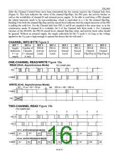
After the Channel Control bytes have been transmitted the bus master receives the Channel Info byte
(Figure 9). This byte indicates the status of the channel flip-flops, the PIO pins, the activity latches as
well as the availability of channel B and external power supply. To be able to read from a PIO channel,
the output transistor needs to be non-conducting, which is equivalent to a 1 for the channel flip-flop.
Reading 0 for both the channel flip-flop and the sensed level indicates that the output transistor of the PIO
is pulling the node low. For the Channel Info byte PIO A and B are sampled at the same time, as in the
synchronous mode. If channel B is available, bit 6 of the Channel Info Byte reads 1. For 1-channel
versions of the DS2406, the PIO B sensed level, channel flip-flop value, and activity latch value should
be ignored. Without an external supply, the supply indication bit (bit 7) reads 0. As long as the voltage
applied to the VCC pin is high enough to operate the device this bit will read 1.
CHANNEL INFO BYTE Figure 9
BIT 7
BIT 6
BIT 5
PIO-B
Activity
Latch
BIT 4
PIO-A
Activity
Latch
BIT 3
PIO B
Sensed
Level
BIT 2
PIO A
Sensed
Level
BIT 1
PIO-B
Channel
BIT 0
PIO-A
Channel
Supply
Indication Channels
0 = no
supply
Number of
0 = channel
A only
Flip-Flop Q Flip-Flop Q
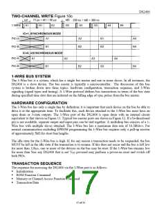
ONE-CHANNEL READ/WRITE Figure 10a
READ (IC=0, Asynchronous Mode)
PIO SAMPLING
PIO
1-WIRE
WRITE (IC=0, Asynchronous Mode)
15 µs < td1 < 60 µs
td1
200 ns < td0 < 300 ns
td0
1-WIRE
PIO
TWO-CHANNEL READ Figure 10b
PIO SAMPLING
1
2
3
4
5
6
7
8
9
PIO-A
PIO-B
IC=1, SYNCHRONOUS MODE
B1
1-WIRE
1-WIRE
A1
A3
B3
B4
A5
A5
B5
A7
B7
A9
A9
IC=0, ASYNCHRONOUS MODE
A1 B2 A3
B6
A7
B8
16 of 31

 DALLAS [ DALLAS SEMICONDUCTOR ]