DS2406
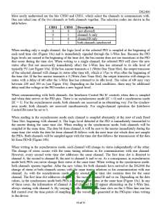
Most easily understood are the bits CHS0 and CHS1, which select the channels to communicate with.
One can select one of the two channels or both channels together. The selection codes are shown in the
table below.
CHS1
CHS0
Description
0
0
1
1
0
1
0
1
(not allowed)
channel A only
channel B only
both channels interleaved
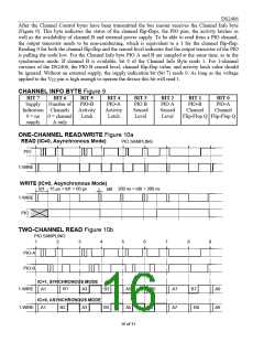
When reading only a single channel, the logic level at the selected PIO is sampled at the beginning of
each read time slot (Figure 10a) and is immediately signaled through the 1-Wire line. Because the PIO
logic levels are sensed at the beginning of the time slot, the bus master does not see transitions at the PIO
that occur during the time slot. When writing to a single channel, the selected PIO will show the new
status after (but not necessarily immediately after) the 1-Wire line has returned to its idle level of
typically 5V (see Figure 10a). If the bus master transmits a 1 (Write One Time Slot), the output transistor
of the selected channel will change its status after time td1, which is 15µs to 60µs after the beginning of
the time slot. If the bus master transmits a 0 (Write Zero Time Slot), the output transistor will change its
status with a delay of td0 after the 1-Wire line has returned to its idle level. The value of td0 may vary
between 200 and 300 ns (see Figure 10a). Depending on the load conditions, there may be additional
delay until the voltage at the PIO reaches a new logical level.
When communicating with both channels, the Interleave Control Bit IC controls when data is sampled
and when data arrives at the PIO pins. There is an asynchronous mode (IC = 0) and a synchronous mode
(IC = 1). For the asynchronous mode, both channels are accessed in an alternating way. For the synchro-
nous mode, both channels are accessed simultaneously. For single-channel operation the Interleave
Control Bit must be set to 0.
When reading in the asynchronous mode each channel is sampled alternately at the start of each Read
Time Slot, beginning with channel A. The logic level detected at the PIO is immediately transmitted to
the master during the same time slot. When reading in the synchronous mode, both channels will be
sampled at the same time. The data bit from channel A will be sent to the master immediately during the
same time slot while the data bit from channel B follows with the next time slot which does not sample
the PIOs. Both channels will be sampled again with the time slot that follows the transmission of the data
bit from PIO-B (Figure 10b).
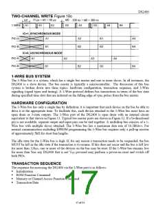
When writing in the asynchronous mode, each channel will change its status independently of the other.
The change of status occurs with the same timing relations as for communication with one channel.
However, every second write time slot addresses the same channel. The first time slot is directed to
channel A, the second to channel B, the next to channel A and so on. As a consequence, in asynchronous
mode both PIOs can never change their status at the same time. When writing in the synchronous mode,
both channels operate together. After the new values for both channels have arrived at the DS2406 the
change of status at both channels occurs with the same timing relations as for communication with one
channel. As with the asynchronous mode, every second write time slot contains data for the same
channel. The first time slot addresses channel A, the second channel B and so on. Depending on the data
values, in the synchronous mode both PIOs can change their status at the same time (Figure 10c). In any
of these cases, the information of channel A and channel B will appear alternating on the 1-Wire line,
always starting with channel A. By varying the idle-time between time slots on the 1-Wire line one has
full control over the time points of sampling and the waveforms generated at the PIO-pins when writing
to the device.
14 of 31

 DALLAS [ DALLAS SEMICONDUCTOR ]