DS2176
SIGNALING SUPERVISION
EXTRACTION
In digital channel banks, robbed–bit signaling data is inserted into the LSB position of each channel
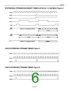
during signaling frames. In 193S framing (FMS=0) applications, A signaling data is inserted into frame 6
and B signaling data is inserted into frame 12. 193E framing (FMS=1) includes two additional signaling
bits: C signaling is inserted into frame 18 and D signaling is inserted into frame 24. This embedded
signaling data is synchronized to system side timing (via the PCM buffer) before being extracted and
presented at outputs A, B, C, and D. Outputs A, B, C, and D are valid for each individual channel time
and are repeated per channel for all frames of the multiframe. In 193S applications, outputs C and D
contain the previous multiframe’s A and B data. Signaling updates occur once per multiframe at the ris-
ing edge of SMSYNC unless prohibited by a freeze.
FREEZE
The signaling buffer allows the DS2176 to “freeze” (pre-vent update of) signaling information during
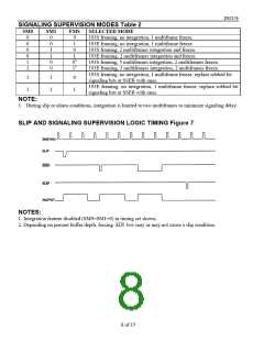
alarm or slip conditions. A slip condition or forcing SIGH low freezes signaling; duration of the freeze is
dependent on SM0 and SM1. Updates will be unconditionally prohibited when SIGH is held low. During
freezing conditions “old” data is recirculated in the output registers and appears at A, B, C and D.
SIGFRZ is held high during the freeze condition, and returns low on the next signaling update. Input to
output delay of signaling data is equal to 1 multiframe (the depth of the signaling buffer) the current
depth of the PCM buffer (1 frame ± approximately 1 frame).
INTEGRATION
Signaling integration is another feature of the DS2176; when selected, it minimizes the impact of random
noise hits on the span and resultant robbed–bit signaling corruption. Integration requires that per–channel
signaling data be in the same state for two or more multiframes before appearing at A, B, C and D. SM0
and SM1 are used to select the degree of integration or to totally by-pass the feature. Integration is limited
to two multi-frames during slip or alarm conditions to minimize up-date delay.
CLEAR CHANNEL CONSIDERATIONS
The DS2176 does not merge the “processed” signaling information with outgoing PCM data at SSER;
this assures integrity of data in clear channel applications. SBIT8 indicates the LSB position of each
channel; when combined with off–chip support logic, it allows the user to selectively re–insert robbed–bit
signaling data into the outgoing data stream.
7 of 15

 DALLAS [ DALLAS SEMICONDUCTOR ]