DS2176
OVERVIEW
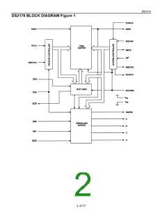
The DS2176 performs two primary functions: 1) synchronization of received T1 PCM data (looped
timed) to host backplane frequencies; 2) supervision of robbed–bit signaling data embedded in the data
stream. The buffer, while optimized for use with the DS2180A T1 Transceiver, is also compatible with
other transceiver devices. The DS2180A data sheet should serve as a valuable reference when designing
with the DS2176.
RECEIVE SIDE TIMING FIGURE 2
DATA SYNCHRONIZATION
PCM BUFFER
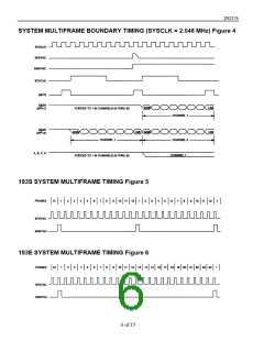
The DS2176 utilizes a 2–frame buffer (386 bits) to synchronize incoming PCM data to the system
backplane clock. The buffer samples data at RSER on the falling edge of RCLK. Output data appears at
SSER and is up-dated on the rising edge of SYSCLK. A rising edge at RMSYNC establishes receive side
frame and multi-frame alignment. A rising edge at SFSYNC establishes system side frame alignment.
The buffer depth is constantly monitored by onboard contention logic; a “slip” occurs when the buffer is
completely emptied or filled. Slips automatically recenter the buffer to a one–frame depth and always
occur on frame boundaries.
SLIP CORRECTION CAPABILITY
The 2–frame buffer depth is adequate for most T–carrier applications where short–term jitter
synchronization, rather than correction of significant frequency differences, is required. The DS2176
provides an ideal balance between total delay and slip correction capability.
BUFFER RECENTERING
Many applications require that the buffer be recentered during system power–up and/or initialization.
Forcing ALN low recenters the buffer on the occurrence of the next frame sync boundary. A slip will
occur during this recentering if the buffer depth is adjusted. If the depth is presently optimum, no
adjustment (slip) occurs. SLIP is held low for 65 SYSCLK cycles when a slip occurs. SLIP is an active–
low, open collector output.
BUFFER DEPTH MONITORING
SMSYNC is a system side output pulse which indicates system side multiframe boundaries. The distance
between rising edges at RMSYNC and SMSYNC indicates the current buffer depth. Slip direction and/or
an impending slip condition may be determined by monitoring RMSYNC and SMSYNC real time.
SMSYNC is held high for 65 SYSCLK cycles.
CLOCK SELECT
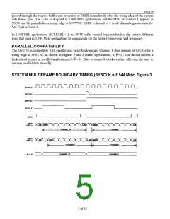
The device is compatible with two common backplane frequencies: 1.544 MHz, selected when
SCLKSEL=0; and 2.048 MHz, selected when SCLKSEL=1. In 1.544 MHz applications the F–bit is
4 of 15

 DALLAS [ DALLAS SEMICONDUCTOR ]