DS2154
12.0 LINE INTERFACE FUNCTIONS
The line interface function in the DS2154 contains three sections: (1) the receiver which handles clock
and data recovery; (2) the transmitter which waveshapes and drives the E1 line; and (3) the jitter
attenuator. Each of these three sections is controlled by the Line Interface Control Register (LICR) which
is described below.
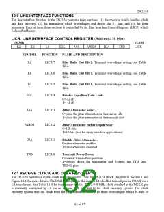
LICR: LINE INTERFACE CONTROL REGISTER (Address=18 Hex)
(MSB)
(LSB)
L2
L1
L0
EGL
JAS
JABDS
DJA
TPD
LICR
SYMBOL
POSITION NAME AND DESCRIPTION
L2
LICR.7
LICR.6
LICR.5
LICR.4
Line Build Out Bit 2. Transmit waveshape setting; see Table
12-2.
L1
L0
Line Build Out Bit 1. Transmit waveshape setting; see Table
12-2.
Line Build Out Bit 0. Transmit waveshape setting; see Table
12-2.
EGL
Receive Equalizer Gain Limit.
0=-12 dB
1=-43 dB
JAS
JABDS
DJA
LICR.3
LICR.2
LICR.1
LICR.0
Jitter Attenuator Select.
0=place the jitter attenuator on the receive side
1=place the jitter attenuator on the transmit side
Jitter Attenuator Buffer Depth Select
0=128-bits
1=32-bits (use for delay sensitive applications)
Disable Jitter Attenuator.
0=jitter attenuator enabled
1=jitter attenuator disabled
TPD
Transmit Power Down.
0=normal transmitter operation
1=powers down the transmitter and 3-states the TTIP and
TRING pins
12.1 RECEIVE CLOCK AND DATA RECOVERY
The DS2154 contains a digital clock recovery system. See the DS2154 Block Diagram in Section 1 and
Figure 12-1 for more details. The DS2154 couples to the receive E1 shielded twisted pair or COAX via a
1:1 transformer. See Table 12-3 for transformer details. The 2.048 MHz clock attached at the MCLK pin
is internally multiplied by 16 via an internal PLL and fed to the clock recovery system. The clock
recovery system uses the clock from the PLL circuit to form a 16 times oversampler which is used to
62 of 87

 DALLAS [ DALLAS SEMICONDUCTOR ]