DS2154
Normally, the clock that is output at the RCLKO pin is the recovered clock from the E1 AMI/HDB3
waveform presented at the RTIP and RRING inputs. When no AMI signal is present at RTIP and RRING,
a Receive Carrier Loss (RCL) condition will occur and the RCLKO will be sourced from the clock
applied at the MCLK pin. If the jitter attenuator is either placed in the transmit path or is disabled, the
RCLKO output can exhibit slightly shorter high cycles of the clock. This is due to the highly oversampled
digital clock recovery circuitry. If the jitter attenuator is placed in the receive path (as is the case in most
applications), the jitter attenuator restores the RCLK to being close to 50% duty cycle. Please see the
Receive AC Timing Characteristics in Section 14 for more details.
12.2 TRANSMIT WAVESHAPING AND LINE DRIVING
The DS2154 uses a set of laser-trimmed delay lines along with a precision Digital-to-Analog Converter
(DAC) to create the waveforms that are transmitted onto the E1 line. The waveforms created by the
DS2154 meet the ITU G.703 specifications. See Figure 12-3. The user will select which waveform is to
be generated by properly programming the L2/L1/L0 bits in the Line Interface Control Register (LICR).
The DS2154 can be set up in a number of various configurations depending on the application. See Table
12-2 and Figure 12-1.
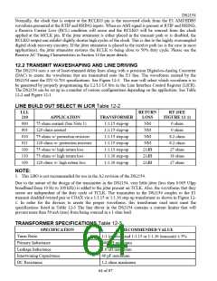
LINE BUILD OUT SELECT IN LICR Table 12-2
LLL
210
RETURN
LOSS
RT (SEE
FIGURE 12-1)
APPLICATION
75 ohms normal (See Note 1)
120 ohms normal
TRANSFORMER
1:1.15 step-up
1:1.15 step-up
1:1.15 step-up
1:1.15 step-up
1:1.15 step-up
1:1.36 step-up
1:1.36 step-up
000
001
010
011
100
110
100
NM
NM
0 ohms
0 ohms
75 ohms w/ protection resistors
120 ohms w/ protection resistors
75 ohms w/ high return loss
75 ohms w/ high return loss
120 ohms w/ high return loss
NM
8.2 ohms
8.2 ohms
27 ohms
18 ohms
27 ohms
NM
21dB
21dB
21dB
NOTE:
1. This LBO is not recommended for use in the A2 revision of the DS2154.
Due to the nature of the design of the transmitter in the DS2154, very little jitter (less then 0.005 UIpp
broadband from 10 Hz to 100 kHz) is added to the jitter present on TCLK. Also, the waveforms that they
create are independent of the duty cycle of TCLK. The transmitter in the DS2154 couples to the E1
transmit shielded twisted pair or COAX via a 1:1.15 or 1:1.36 step up transformer as shown in Figure 12-
1. In order for the devices to create the proper waveforms, this transformer used must meet the
specifications listed in Table 12-3 The line driver in the DS2154 contains a current limiter that will
prevent more than 50 mA (rms) from being sourced in a 1 ohm load.
TRANSFORMER SPECIFICATIONS Table 12-3
SPECIFICATION
RECOMMENDED VALUE
1:1 (receive) and 1:1.15 or 1:1.36 (transmit) ± 5%
600 uH minimum
Turns Ratio
Primary Inductance
Leakage Inductance
Intertwining Capacitance
DC Resistance
1.0 uH maximum
40 pF maximum
1.2 ohms maximum
64 of 87

 DALLAS [ DALLAS SEMICONDUCTOR ]