DS1921H/Z
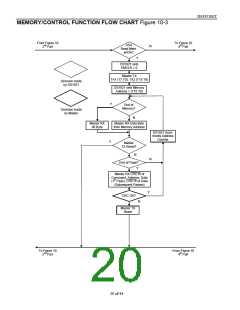
Read Memory with CRC [A5h]
The Read Memory with CRC command is used to read memory data that cannot be packetized, such as
the register page and the data recorded by the device during a mission. The command works essentially
the same way as the simple Read Memory, except for the 16-bit CRC that the DS1921H/Z generates and
transmits following the last data byte of a memory page.
After having sent the command code of the Read Memory with CRC command, the bus master sends a 2-
byte address (TA1 = T7:T0, TA2 = T15:T8) that indicates a starting byte location. With the subsequent
read data time slots the master receives data from the DS1921H/Z starting at the initial address and
continuing until the end of a 32-byte page is reached. At that point the bus master will send 16 additional
read data time slots and receive an inverted 16-bit CRC. With subsequent read data time slots the master
will receive data starting at the beginning of the next page followed again by the inverted CRC for that
page. This sequence will continue until the bus master resets the device.
With the initial pass through the Read Memory with CRC flow, the 16-bit CRC value is the result of
shifting the command byte into the cleared CRC generator followed by the two address bytes and the
contents of the data memory. Subsequent passes through the Read Memory with CRC flow will generate
a 16-bit CRC that is the result of clearing the CRC generator and then shifting in the contents of the data
memory page. After the 16-bit CRC of the last page is read, the bus master will receive logical 0s from
the DS1921H/Z and inverted CRC16s at page boundaries until a reset pulse is issued. The Read Memory
with CRC command sequence can be ended at any point by issuing a reset pulse.
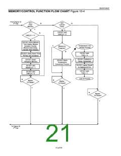
Clear Memory [3Ch]
The Clear Memory command is used to clear the Sample Rate, Mission Start Delay, Mission Time
Stamp, and Mission Samples Counter in the register page and the Temperature Alarm Memory and the
Temperature Histogram Memory. These memory areas must be cleared for the device to be set up for
another mission. The Clear Memory command does not clear the datalog memory or the temperature and
timer alarm flags in the Status Register. The RTC oscillator must be on and have counted at least 1
second, before issuing the command. For the Clear Memory command to function the EMCLR bit in
Control Register must be set to 1, and the Clear Memory command must be issued with the very next
access to the device’s memory functions. Issuing any other memory function command will reset the
EMCLR bit. The Clear Memory process takes 500µs. When the command is completed the MEMCLR bit
in the Status Register will read 1 and the EMCLR bit will be 0.
Convert Temperature [44h]
If a mission is not in progress (MIP = 0) the Convert Temperature command can be issued to measure the
current temperature of the device. The result of the temperature conversion will be found at memory
address 211h in the register page. This command takes maximum 360ms to complete. During this time
the device remains fully accessible for memory/control and ROM function commands.
22 of 44

 DALLAS [ DALLAS SEMICONDUCTOR ]