DS1921H/Z
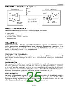
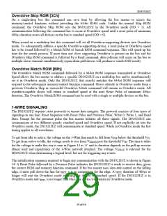
HARDWARE CONFIGURATION Figure 12
VPUP
BUS MASTER
DS1921 1-Wire PORT
RPUP
RX
DATA
RX
TX
5µA
Typ.
TX
RX = RECEIVE
100
MOSFET
Ω
TX = TRANSMIT
Open Drain
Port Pin
TRANSACTION SEQUENCE
The protocol for accessing the DS1921H/Z via the 1-Wire port is as follows:
ꢀꢁInitialization
ꢀꢁROM Function Command
ꢀꢁMemory/Control Function Command
ꢀꢁTransaction/Data
INITIALIZATION
All transactions on the 1-Wire bus begin with an initialization sequence. The initialization sequence
consists of a reset pulse transmitted by the bus master followed by presence pulse(s) transmitted by the
slave(s).The presence pulse lets the bus master know that the DS1921H/Z is on the bus and is ready to
operate. For more details, see the 1-Wire Signaling section.
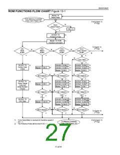
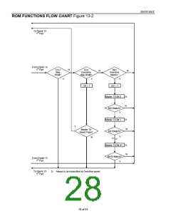
ROM FUNCTION COMMANDS
Once the bus master has detected a presence, it can issue one of the seven ROM function commands. All
ROM function commands are eight bits long. A list of these commands follows (refer to flowchart in
Figure 13).
Read ROM [33h]
This command allows the bus master to read the DS1921H/Z’s 8-bit family code, temperature range code,
plus unique 36-bit serial number and 8-bit CRC. This command can only be used if there is a single slave
on the bus. If more than one slave is present on the bus, a data collision will occur when all slaves try to
transmit at the same time (open drain will produce a wired-AND result). The resultant family code and
temperature range code plus 36-bit serial number will result in a mismatch of the CRC.
Match ROM [55h]
The Match ROM command, followed by a 64-bit ROM sequence, allows the bus master to address a
specific DS1921H/Z on a multidrop bus. Only the DS1921H/Z that exactly matches the 64-bit ROM
sequence will respond to the following memory function command. All other slaves will wait for a reset
pulse. This command can be used with a single or multiple devices on the bus.
25 of 44

 DALLAS [ DALLAS SEMICONDUCTOR ]